Table of Contents
Advertisement
Quick Links
Instruction Manual for MODEL A7X1A-X(Load Cell Input)
Operation Manual for the A7000 Series
Load Cell Input: A7X1A-X
!
CAUTIONS
(1) Application of voltage or current exceeding the maximum allowable value to the
input section may damage the instrument.
(2) Use the supply voltage in the allowable range. Using it out of this range may
result in fire, electric shock, or an instrument failure.
(3) Please note that the information contained in this manual is subject to change
due to product improvements without notice.
(4) Every effort has been made to ensure accuracy in the presentation of this
manual. However, should you have any questions or should any errors or
omissions come to your attention, please contact your sales representative or our
sales office directly.
(5) After reading, keep this manual nearby so that you can refer to it as needed.
1. Check before Use
Thank you for purchasing our A7000 series. The operator who
uses the instrument should keep this manual on hand. When you
receive the product, make sure that you have all the parts and that
none have been damaged during transportation. If any part is
damaged or missing, contact your sales representative or our sales
office directly.
1.1. Type Configuration
The type configuration of the A7000 series is as shown below.
Check that there is no difference in the type or specifications
between the product you ordered and the product you have
received.
A7
1
-
Power
1:AC power(100 to 240V AC,50/60Hz)
2:DC power(12 to 48V DC)
Input
1:DC voltage measurement(±100mV,±1V,±10V,±100V,or
±700V measurement
2:DC small current measurement(±100μA,±1mA,±10mA,
or±100mA measurement
3:DC large current measurement(±1A or ±2Ameasurement)
4:AC voltage measurement(100mV,1V,10V,100V,
or 700V measurement)
5:AC small current measurement(100μA,1mA,10mA,or 100mA
measurement)
6:AC large current measurement(1A or 5Ameasurement)
7:Resistance measurement
8:Temperature measurement(TC,RTD)
9:Frequency measurement
A:Load cell input
B:Process signal measurement(1 to 5V,±5V ,4 to 20mA,or
±20mA measurement)
Output
0:None
1:Relay contact output
2:Photocoupler output
3:BCD output (TTL)
4:BCD output (Open collector)
5:BCD output (TTL)
+ Photpcoupler output
6:BCD output (Open collector) + Photpcoupler output
7:Analog output
8:Analog output + Photocoupler output
9:RS-232C
A:RS-485
B:RS-232C + Photocoupler output
C:RS-485 + Photocoupler output
WATANABE ELECTRIC INDUSTRY CO.,LTD.
2. Mounting Method
2.1. Panel Cutout Dimensions
For panel cutout made when mounting the A7000 series
measuring unit, follow the figure below.
+0.7
68
-0
96 mm or more
2.2. Panel Mounting Method
To mount the A7000 series measuring unit onto a panel, remove
the mounting band from the main unit, fit the unit into the panel from
the front of the panel, and fix it using the mounting band removed
from the rear of the panel. If you wish to increase the strength of the
mounting, attach fixing supports with screws as shown in the figure
below. For fixing supports and screws, contact your sales
representative or our sales office.
Mounting band
CAUTIONS
!
(1) Mount the instrument securely on a surface that will be able to bear its weight.
Insufficient strength for mounting or incorrect mounting may result in the instrument
falling and injuring personnel.
(2) The A7000 series has no power switch. Connecting power to the instrument
makes the product immediately operable.
(3) If the instrument is installed inside equipment to heat radiation, etc., and ensure
that the in-equipment temperature does not rise above 50°C.
3. Description of Terminals and Connection
Output section (different configuration for BCD
output)
Input section
3.1. Connecting Power
Recommended
Torque:0.5Nm
①
②
100 to 240V AC(50/60Hz)
12 to 48V DC
+
Name
Terminal No.
1
Power
Power connection terminal. 0V for DC driving
Power connection terminal. +V for DC driving
2
Power
1/12
Lugs
Plastic screw
Fixing support
M3×20
Power section
Applicable crimp terminal
5.8 or less
5.8 or less
Description
UW-33813L
2020.12
Advertisement
Table of Contents

Related Manuals for WATANABE ELECTRIC INDUSTRY A7000 Series


Summary of Contents for WATANABE ELECTRIC INDUSTRY A7000 Series
- Page 1 Check that there is no difference in the type or specifications falling and injuring personnel. between the product you ordered and the product you have (2) The A7000 series has no power switch. Connecting power to the instrument makes the product immediately operable. received.
- Page 2 COM. Digital Zero terminal. Enabled when it has the same potential as, * In the A7000 series, sensor power needs to be set using calibration data. or is shorted with, terminal COM. The unit is set to 5V at factory shipment.
-
Page 3: Analog Output Unit
Instruction Manual for MODEL A7X1A-X(Load Cell Input) 3/12 Analog Output Unit RS-485 Unit 3.3.4. 3.3.6. Adaptable wire: AWG24 to AWG16 Adaptable wire: AWG24 to AWG16 Recommended torque : 0.18Nm Recommended torque : 0.18Nm 1 2 3 4 5 6 7 8 9 10 11 12 13 14 15 1 2 3 4 5 6 7 8 9 10 11 12 13 14 15 Term. -
Page 4: Part Names And Their Functions
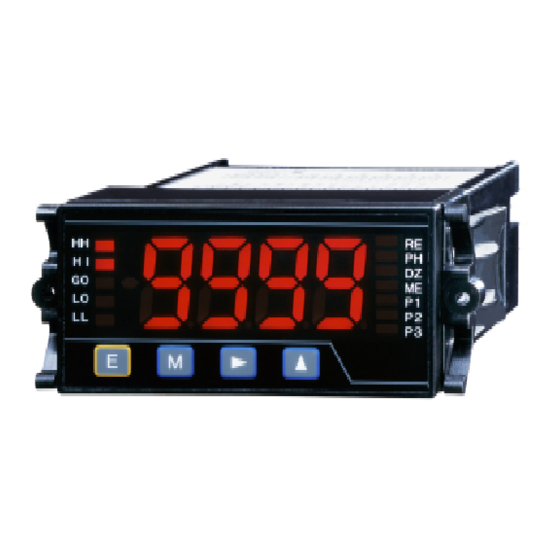
Instruction Manual for MODEL A7X1A-X(Load Cell Input) 4/12 4. Part Names and their Functions ① ② ③ Loca- Name Main Functions tion ① Judgment Monitor Indicates judgment results when the unit is used as a meter relay. RE HH PH Main Monitor ②... -
Page 5: Calibration Data
Each parameter has a protect level that has been set up. Setting the protect level of condition data allows the settable protect level of The A7000 series parameters are classified into the following groups parameters to be limited. (For the settable protect level of each depending on the main objective: parameter, see P.L for the list of parameters in 5.1.) - Page 6 Instruction Manual for MODEL A7X1A-X(Load Cell Input) 6/12 5.4. Shifting to the Parameter Setting Mode 5.6. Scaling Data Setting Procedure Measurement operation This section describes the concept of analog output scaling and an example of setting the decimal point. Take the same steps for other Pressing for a prolonged time parameters.
- Page 7 Instruction Manual for MODEL A7X1A-X(Load Cell Input) 7/12 5.7. Comparator Data Setting Procedure Tolerance Judgment Type 5.7.2. The A7000 can comparison operation a vertical judgment or a The tolerance judgment type allows you to set a nominal value and its tolerance judgment with the comparison output type of a compartor tolerances (±XX%) to make judgment on the basis of the judgment data setup.
- Page 8 Instruction Manual for MODEL A7X17-X(Load Cell Input) 8/12 (From the previous page) 5.8. Calibration Data Setting Procedure There are two calibration methods in calibration using a sensor : an equivalent calibration method and an actual loading calibration method. The equivalent calibration method carries out calibration ⑮...
-
Page 9: External Control Function
⑩ Press the Mode key to return to the setting menu. (In this setting example, the display returns to the first input setting The A7000 series allows four judgment values of HH, HI, LO, and menu.) LL to be set up with respect to the measured value (indicated value) and the judgment result to be output by relay contact output or photocoupler (when the comparison output unit has been installed). -
Page 10: Comparison Output
Instruction Manual for MODEL A7X1A-X(Load Cell Input) 10/12 7.3. Analog Output Function 8.3. Output Specifications The A7000 series can output an analog signal with respect to the Comparison Output 8.3.1. indicated value (when the analog output unit has been installed). -
Page 11: Analog Output
*1 Set sampling Delimiter CR+LF/CR This is the practical sampling rate of the A7000 series that is set using the AVG * For more information on the communications function such as the send/receive format parameter of condition data (see the table below). -
Page 12: Error Messages
If a failure occurs during this period that is clearly judged to Indicates that a signal exceeding the measurement range has been applied. be caused by a defect ascribable to Watanabe Electric Industry, we will repair the failure or replace any defective parts without charge.
Need help?
Do you have a question about the A7000 Series and is the answer not in the manual?
Questions and answers