Table of Contents
Advertisement
Quick Links
Instruction Manual for MODEL
SET POINT COMPARATOR
AM-215A INSTRUCTION MANUAL
E
Caution
!
(1)
The equipment may be damaged if the input current or voltage exceeds
the maximum allowed value.
(2)
Only use a supply voltage which is in the usable voltage range. Using a
voltage outside this range may result in fire, electric shock, or damage to
the equipment.
(3)
Please note that the contents of this manual may be changed without
notice due to product modifications.
(4)
In preparing this manual, we made every effort to provide the best manual
possible. Please contact your dealer or Watanabe if you notice any
deficiencies, errors, omissions, etc.
(5)
After you finish reading the manual, keep it handy for future access.
Before using the product
1.
Thank you for purchasing the AM-215A Series. Keep this operating manual handy
so that you can refer to it in the future. Check the contents of your package
and contact your dealer or Watanabe if you notice any problems (e.g., equipment
damage).
1.1.Equipment numbers
The equipment numbers used with the AM-215A Series follow the chart shown
below. Make sure the product you selected when you placed your order has the
same model number and specifications as the product you received.
A M - 2 1 5
A
- X X - X X
Basic model
Series name
1.2. Standard accessories check
The AM-215A package includes an operating manual (this document) and one unit
seal.
Panel cutting dimensions
2.
2.1. Panel cutting dimensions
Follow the dimensions shown in the diagram below in cutting the panel in order
to install the AM-215A Series.
+0.5
45.0
-0
MIN
57
AM-215A UL
AL1 AL2
M
Comparator output
1:Relay contact output
2:Photocoupler output
Option output
1:None
4:RS-485 interface
6:Analog output(4-20mA)
7:Analog output(0-10V)
Input range
11:11Range(+-99.99mV)
12:12Range(+-999.9mV)
13:13Range(+-9.999V)
1V:1VRange(1-5V)
2A:2ARange(4-20mA)
* Recommended panel
thickness: 1-8 mm
WATANABE ELECTRIC INDUSTRY CO., LTD.
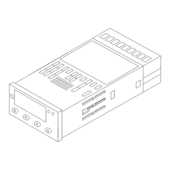
2.2.
External dimensions
E
M
48.0
3.5
84.3
2.3.
Panel attachment procedure
After removing the attachment bands from the main unit, insert the unit
through the front of the panel, and fasten it from the rear side of the panel
using the attachment bands.
Caution
!
(1)
Make sure the installation location is strong enough to support the unit's weight. If it is
not strong enough, or if the unit is not properly attached, the display may fall, possibly
resulting in injury.
(2) When installing the unit in a system, be sure there is sufficient heat dissipation so that the
temperature inside the system does not reach or exceed 50°C.
Description of terminals and connection
3.
procedure
EXC
+24V
0V
10
11
1
2
HI
LO
INPUT
Connection using wire
Thickness: AWG28-16
Wire exposed length:
5-6 mm
Dimensions of terminal
block opening
1.8
AM-215 terminal block side view
①②:Input signals
•
Make the input signal lines as short as possible. Keep them away from other
signal lines.
•
If there is a lot of external noise, use a two-wire shielded cable and form
a single connection between the outer sheath and the LO side at the signal
source.
AL1 AL2
▲
OUT3
OUT2
OUT1
(c)
(e)
(c)
(e)
(c)
(e)
COM
a
c
a
c
a
c
12
13
14
15
16
17
18
POWER
!
3
4
5
6
7
8
9
+
-
DZ
0V
+V
TERMINA
ANALOG
POWER
TOR
OUT
or
RS485
Connection using rod
terminal
M2.5 Phillips screwdriver
Recommended
torque: 0.4 Nm
UX-34107k
2016.01
1/4
Advertisement
Table of Contents

Related Manuals for WATANABE ELECTRIC INDUSTRY AM-215A


Summary of Contents for WATANABE ELECTRIC INDUSTRY AM-215A
-
Page 1: External Dimensions
Before using the product Thank you for purchasing the AM-215A Series. Keep this operating manual handy so that you can refer to it in the future. Check the contents of your package and contact your dealer or Watanabe if you notice any problems (e.g., equipment damage). -
Page 2: Parameter Setting
⑧, ⑨: Power source terminals (DC POWER) · A power source is connected to a power source terminal. The 4.1.1 Condition Data Setting AM-215A does not have a power switch. The power is turned ON as soon as the power source is connected. (Measurement operation) If M key is pushed in the state of each menu name or there is no key operation ⑩, ⑪: EXC (sensor power source) - Page 3 F S C : 5000 5000 ●Comparative operation type F I N : 9999 O F S : 0 In the AM-215A, use the comparator data to select one type of 3000 O I N Input comparative operation from the three types below:...
-
Page 4: Error Messages
Instruction Manual for MODEL AM-215A UL Error messages Comparator unit Control method Microcomputer computation The error message of AM-215A and the solution at the time of an error Setting range -9999 to +9999 are as follow. Comparator operation Depends on sampling speed. -
Page 5: Digital Panel Meter
*Setting condition (rectifying point n input value) > (rectifying point n-1 input value) (Rectifying point The output value (display value before linearity -9999~+9999 16 output value) compensation) of the rectifying point 16 is inputted. (Measurement operation) 2014.04 WATANABE ELECTRIC INDUSTRY CO., LTD UX-48894c... - Page 6 User’s Manual AM-215A Series RS-485 AM-215A Series RS-485 User’s Manual Overview This manual explains the specifications of the communication functions provided by the AM -215A series of digital panelmeters. It also explains how to handle the AM -215A series. Specifications...
- Page 7 The baud rate, data length, parity bit, stop bit, delimi ter, and device ID are the user-selectable parameters of the communication functions provided by the AM -215A panelmeter. For details on how to set the parameters, see the user’s manual of the AM-215A main unit. 5 RS-485 Transmission/Reception Formats 5.1 Establishing and Releasing the Communication Link...
-
Page 8: Communication Commands
User’s Manual AM-215A Series RS-485 5.3. BCC Checksum As a means of error detection, a block check character (BCC) checksum is added to the RS -485 communication function of the AM-215A panelmeter. See the following illustrations for details on the transmission and reception formats. - Page 9 User’s Manual AM-215A Series RS-485 Digital zero remote control response CR LF CR LF (Response with the status of the digital zero function being set to OFF by remote control) CR LF (Response with the status of the digital zero function being set to ON by...
- Page 10 User’s Manual AM-215A Series RS-485 Step width response CR LF CR LF (Response with the status of the step width being 1.) CR LF (Response with the status of the step width being 0.) Step width setting CR LF CR LF (Sets the step width to 1.)
- Page 11 User’s Manual AM-215A Series RS-485 Comparator data response CR LF CR LF Note: The reading of the main unit changes to COM the moment it receives a COM command. (Response with the status of the conparative output type function being set to HI-GO-LO.)
- Page 12 User’s Manual AM-215A Series RS-485 Scaling data response CR LF CR LF Note: The reading of the main unit changes to MET the moment it receives an MET command. (Response with a full-scale reading.) CR LF CR LF (Response with a full-scale input value.)
- Page 13 User’s Manual AM-215A Series RS-485 Common response CR LF (Normal response) CR LF (Response to, e.g., undefined commands.) CR LF (Response to out-of-range data or data that do not meet setting conditions.) CR LF (Response when there is any communication parameter failure.) Note: Under normal conditions, this response is made only once.
Need help?
Do you have a question about the AM-215A and is the answer not in the manual?
Questions and answers