Table of Contents
Advertisement
Quick Links
MODEL WPMZ-1-□□□-□□-□□□
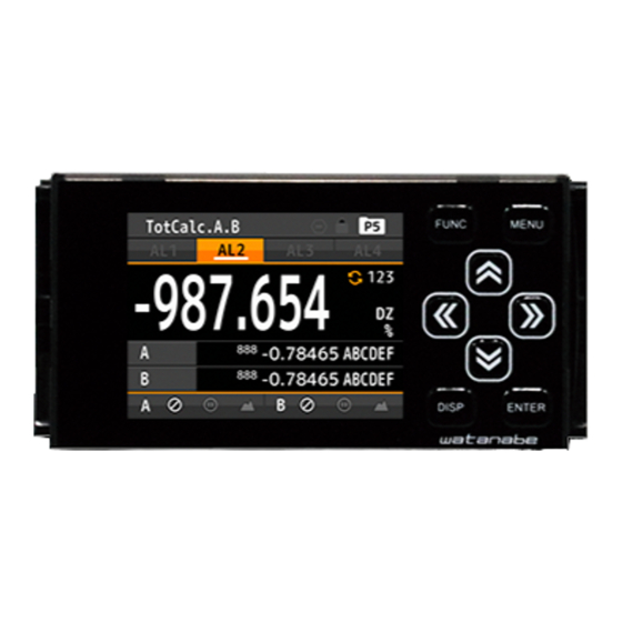
Graphical Digital Panel Meter
WPMZ-1-□□□-□□-□□□
Quick instruction manual
Thank you for purchasing the WPMZ graphical digital panel meter.
This manual is a quick instruction manual only for preparation,
connection and basic condition settings of the WPMZ. For the all
functions of the WPMZ, please refer to a detailed instruction
manual which can be downloaded from our homepage.
For models with RS communication functions, please refer to
"Modbus communication manual" or "RS-232C communication
manual" which also can be downloaded from our homepage.
(https://www.watanabe-electric.co.jp/en/)
Checks before suppling power, preparations, wiring
1. CHECKING THE PRODUCT
1-1. MODEL CODES
Please check that the product has been delivered matches the
model code ordered in reference to "18. SPECIFICATIONS".
2. PRECAUTIONS FOR USE
2-1. ENVIRONMENTS AND CONDITIONS OF USE
Please do not use the product under the following circumstances.
It might cause malfunctions and shortening the life of the
product.
1)
Ambient temperature of out of -5 to
2)
Ambient humidity of out of 35 to 85%, or freezing
condensing
3)
Excessive dust or metal particles
(Storing in a dust-proof chassis and a countermeasure
against heat dissipation are required.)
4)
Environment of corrosive gas, salty air or oily smoke
5)
Environment of much vibration or impact
6)
Environment of rain or water drops (except the front
panel)
7)
Environment of strong electromagnetic field or much
exogenous noises.
2-2. INSTALLATION AND CONNECTION
1)
Please read this manual before the installation and the
connection of wires. And they should be performed by a
person having a specialized technique. In addition, the
insulation class of the WPMZ is as shown by the figure
below. Please confirm that the insulation class satisfies a
use condition prior to the installation.
Reinforced Insulation
Operational Insulation
Comparative outputs, External
control inputs, Analog output, BCD
AC
output,RS-232C
power
Input Ach
Go output
Comparative outputs, External
control inputs, Analog output, BCD
DC
output,RS-232C
power
Input Ach
GO output
2)
Do not wire the power supply line, input signal lines and
output signal lines near noise sources or relay drive lines.
3)
Bundling or containing in a same duct with lines including
noises might cause malfunctions.
4)
The WPMZ becomes available functionally right after
power activation, but requires 30 minutes' warming to
satisfy all performance requirements.
Note: The inputs "A channel" and "B channel" may be
abbreviated to "Ach" and "Bch" in this manual.
2-3. CHECKING BEFORE USE
Install the WPMZ under the environments and conditions of use
which meet requirements.
If you find any damage to the product or any problem, please
contact to your dealer or our company directly.
50°C
Basic Insulation
【Open-collector output products】
RS-485
Modbus
RTU
Input Bch
Go output
RS-485
Modbus
RTU
Input Bch
GO output
3. HOW TO INSTALL (PANEL CUT DIMENTIONS)
To install the WPMZ, panel cut dimensions are as shown by the
figure below.
+0.8
92
-0
120mm min.
4. CONNECTING TERMINALS
4-1. BACK VIEW
UPPER ROW TERMINALS
Ach inputs
Comparetive output/External control input
LOWER ROW TERMINALS
4-2. WIRING TO SCREWLESS TERMINALS
Pushing the wire release button with a flat-blade screwdriver,
insert the wire to the wire insert hole deeply and then release
the button.
( Suitable tool for pushing buttons : flat-blade screwdriver
blade width 2.5mm)
4-3. CONNECTION FOR LOWER ROW TERMINALS
(COMPARATIVE OUTPUT/EXTERNAL CONTROL
INPUT, POWER)
4-3-1. Comparative Output / External Control Input
*Screwless connector
Open collector outputs
1 2 3 4 5 6 7 8 9
① ② ③ ④ ⑤ ⑥
No.
Name
1
AL1
AL1 open-collector output (collector)
2
AL2
AL2 open-collector output (collector)
3
AL3
AL3 open-collector output (collector)
4
AL4
AL4 open-collector output (collector)
Common terminal for PNP output (emitter)
5
AL+COM
(NPN output : no connection)
Common terminal for NPN output (emitter)
6
AL-COM
(PNP output : GND for PNP)
7,8
COM
Common terminal for external control inputs
9
EXT 1
External control input No.1
10
EXT 2
External control input No.2
11
EXT 3
External control input No.3
12
EXT 4
External control input No.4
13
EXT 5
External control input No.5
Bch inputs
MIDDLE ROW
TERMINALS
outputs
Power
Wire insert hole
Wire release button
※⑥、⑦、⑧ : connected internally
External control inputs
10 11 12 13
Suitable wire:AWG 24 to16
Description
IM-0880-02
1/12
Advertisement
Table of Contents

Related Manuals for WATANABE ELECTRIC INDUSTRY WPMZ-1 Series


Summary of Contents for WATANABE ELECTRIC INDUSTRY WPMZ-1 Series
- Page 1 MODEL WPMZ-1-□□□-□□-□□□ 1/12 3. HOW TO INSTALL (PANEL CUT DIMENTIONS) Graphical Digital Panel Meter To install the WPMZ, panel cut dimensions are as shown by the WPMZ-1-□□□-□□-□□□ figure below. Quick instruction manual +0.8 Thank you for purchasing the WPMZ graphical digital panel meter. This manual is a quick instruction manual only for preparation, connection and basic condition settings of the WPMZ.
- Page 2 MODEL WPMZ-1-□□□-□□-□□□ 2/12 4-4-3. Process Input / GO Output / Sensor Power Supply 【Relay output products】 *Screwless connector Relay outputs External control inputs Ach Process input Bch Process input ※⑮、⑱ : connected internally ※ 、 : connected internally 22 25 1 2 3 4 5 6 7 8 9 10 11 12 13 14 15 16 17 18 19 21 22 23 24 25 26...
-
Page 3: Names Of Each Part
MODEL WPMZ-1-□□□-□□-□□□ 3/12 4-5-2. BCD Output 4-5-3. RS-232C 28 29 30 31 32 33 2 8 2 8 2 8 2 8 Suitable wire:AWG24 to 16 ●WPMZ-1-□□□-4□-□□□ 1 4 1 4 1 4 1 4 Name Description receive data terminal transmit data terminal Suitable wire:AWG#28 flat cable(7/0.127mm) common terminal for communication function... -
Page 4: Enter Key
MODEL WPMZ-1-□□□-□□-□□□ 4/12 5-2. EXPLANATION OF ICONS 5-2-2. Key Operation Icons on The Setting Display 5-2-1. ICONS FOR EXTERNAL CONTROL These are icons when external control is ON. Icon Meaning Icon Meaning Icon Meaning ARROW key MENU key (LEFT) Indicates pattern No. in use. ARROW key FUNC key Indicates key lock function is effective. - Page 5 MODEL WPMZ-1-□□□-□□-□□□ 5/12 3rd Layer 4th Layer (setting values) 1st Layer 2nd Layer Remarks (setting items) Initial values Settable values 1stIn: 0 1stOut: 0 2ndIn:1000 LinearizePoint Each: ±99999 Enable only if [InputCorrect] is [Linearize]. 2ndOut:1000 …… DC InputA 16thIn:15000 16thOut:15000 DC InputB DispShift ±99999...
- Page 6 MODEL WPMZ-1-□□□-□□-□□□ 6/12 3rd Layer 4th Layer (setting values) 1st Layer 2nd Layer Remarks (setting items) Initial values Settable values ModbusRTU/OriginalCommand/OriginalO Protocol Modbus-RTU Select a protocol. utput Baudrate 19200bps 9600bps/19200bps/38400bps Select a baudrate. Parity Even None/Even/Odd Select a type of parity bit. Enable when Protocol is OriginalCommand 2.Output RS-232C Com...
-
Page 7: Setting Examples
MODEL WPMZ-1-□□□-□□-□□□ 7/12 8. BASIC OPERATIONS FOR SETTING DISPLAYS Basic operations for setting displays are shown as below. The following is an example for changing the voltage of sensor power supply. Measurement Display Setting Process Sensor MENU 1. Input InputA Power MENU Layer... - Page 8 MODEL WPMZ-1-□□□-□□-□□□ 8/12 assigned to comparative outputs. 12-3. COMPARISON JUDGEMENT VALUE 13-3. DISPLAY HOLD FUNCTION The comparison judgement value is a threshold value to judge. Display hold function holds display value. While this function is How to set the value is shown below. valid, measurement action is performed internally and the latest *The following is an explanation for the compare mode of “Level measurement value is displayed when the function become...
- Page 9 MODEL WPMZ-1-□□□-□□-□□□ 9/12 14. SHORTCUT FUNCTION 15-3. INITIALIZE TO USER DEFAULTS External control functions are registered to arrow keys and are Beside of initializing to factory defaults, current setting values performed not by the terminal control but by the operation of the can be saved as user default data and setting values will be keys initialized to the data.
-
Page 10: Basic Specifications
MODEL WPMZ-1-□□□-□□-□□□ 10/12 Power AC power(WPMZ-1-1**-**-***) : 18. SPECIFICATIONS consumption At AC100V:10VA max At AC240V:14VA max MODEL CODES DC power(WPMZ-1-3**-**-***) WPMZ At DC12V:6W max, DC power(WPMZ-1-4**-**-***) At DC24V:6W max, At DC48V:6.5W max External 96mm(W)×52mm(H)×145mm(D) : dimension’s Weight Approx. 350g : Withstand AC power (WPMZ-1-1**-**-***)... -
Page 11: Output Specifications
MODEL WPMZ-1-□□□-□□-□□□ 11/12 Conversion ⊿∑conversion method Outside of zone alarm : method Condition of comparison Result Input signal Single ended : Display value > AL1 upper limit or Sampling rate Max. 4000 times/sec (1ch product) : lower limit > value Max. - Page 12 Cable length Max.1.2km (total) ※Conforming CE mark, less than 30m : The contents of this instruction manual are subject to change without prior notice. WATANABE ELECTRIC INDUSTRY CO.,LTD. http://www.watanabe-electric.co.jp 6-16-19, JINGUMAE, SHIBUYA-KU, TOKYO 150-0001, JAPAN TEL +81-3-3400-6147 FAX +81-3-3409-3156 IM-0880-02...
Need help?
Do you have a question about the WPMZ-1 Series and is the answer not in the manual?
Questions and answers