Advertisement
Quick Links
Operation Manual MODEL A2200 Series
Digital Panel Meter
Model A2200 Series
Operation Manual
!
CAUTIONS
(1) Using the product in ways other than specified may result in a failure of the
protection provided for the product.
(2) Please note that the information contained in this manual is subject to change
without notice due to product improvements.
(3) Every effort has been made to ensure accuracy in the presentation of this manual.
Should any errors or omissions come to your attention, or should you have any
questions, however, please contact your sales representative or our sales office
directly.
(4) After reading this manual, keep it nearby so that you can refer to it as needed.
(5) In order to prevent damage by static electricity, before changing the decimal
point position, touch a metal existing around you with the hand to discharge
static electricity charged on your body.
1 Check before Use
Thank you for purchasing our A2200 series. When you receive
the product, make sure that you have all the parts and that
none have been damaged during transportation. I f any part
is damaged or missing, contact your sales representative or
our sales office directly.
2 Overview
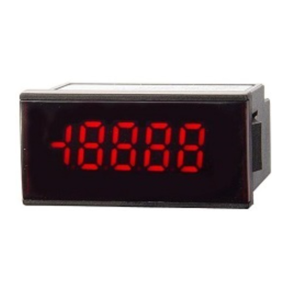
The A2200 series digital power meter is a compact 4 1/2 -digit
indicating meter that meets DIN standards for external
dimensions. Power is +5 V to 2 4 V DC type. The maximum
indication is a 19999.
2.1 Type Configuration
A
2
2
2
0
-
Luminace :
* High luminance LED becomes about three
Input range :
* The CE mark doesn't adhere to 14 rangees.
Power
2.2 Checking the Accessories
The A2200 series comes with an Operation Manual (1 copy).
Should you have any questions about the manual, please
contact your sales representative or our sales office
directly.
2.3 Mounting Method
2.3.1 Panel Cutout Dimensions
For the panel cutout when mounting the A2 200 series panel
meter, follow the figure below.
+0.6
45
-0
No sign LED Standard luminance
:
H
LED High luminance
times brightness for standard luminance.
(Depend on our comparison.)
12 12 range (±1.9999V)
13 13 range (±19.999V)
14 14 range (±199.99V)
:
2 Isolated power (+5V to 24V)
65mm or more
WATANABE ELECTRIC INDUSTRY CO., LTD
2.3.2 Panel Mounting Method
To mount the A2200 series panel meter onto a panel, press
the snaps on the sides of the case and fit the meter onto
the panel from the front (see figure below).
Snap
Panel meter
2.4 Description of Terminals
2.4.1 Terminal Connection Diagram
1
2
3
4
5
2.4.2 Connection Method
The connection terminal of the A2 200
series panel meter's terminals is
located inside the case.
When connecting a wire, insert it into
the case from the rear of the meter and
fasten it with a screw using a Phillips
screwdriver from the top of the rear of
the case.
Appropriate leads: 16 to 22 AWG
Recommended covering stripping
size: 6 to 7 mm
3 Decimal-point Setting Method
Insert a flat-blade screwdriver or the like into the small
hole in the lower part of the front panel acrylic section
and pry the front panel out.
When putting the front panel back into the instrument,
fit in the lugs in the upper part of the acrylic section
first.
The stud pin at the lower right is a decimal-point switch.
Short the short-circuit sockets concerned to
light the decimal point.
10
3
-digit decimal point
10
4
-digit decimal point
!
* CAUTION
Be sure to turn off the panelmeter before changing the
decimal point position.
4 Calibration Method
To calibrate this panel meter, a voltage/current generator
with an accuracy of ±0.01% or higher is required. Calibrate
it using the following procedure under ambient conditions
of 23℃ ±5℃ and 35 to 85% R.H.
(1) Connect power to the meter and run it for more than 20
minutes.
(2) Conduct a full-scale adjustment
Apply a voltage or current equivalent t o a full scale of
19900 to the input section and turn the full -scale volume
knob (figure below) so that the reading shows "1990 0."
Then apply voltage or current of the negative polarity
to check that the reading shows "-19900±(0.1% of FS)."
Snap
Mounting panel
(Recommended panel thickness:
0.8 to 3.5 mm)
Terminal
Name
Description
No.
+ side of input signal
1
HI
2
LO
- side of input signal
3
HOLD
External control terminal
- side of power terminal
4
0V
+ side of power terminal
5
+V
10
2
-digit decimal point
10
1
-digit decimal point
Full-scale volume knob
UW-33507r
2021.07
Advertisement

Related Manuals for WATANABE ELECTRIC INDUSTRY A2200 Series


Summary of Contents for WATANABE ELECTRIC INDUSTRY A2200 Series
- Page 1 3 Decimal-point Setting Method 2 Overview The A2200 series digital power meter is a compact 4 1/2 -digit indicating meter that meets DIN standards for external Insert a flat-blade screwdriver or the like into the small dimensions.
- Page 2 Case to each terminal 1500VAC f or 1minute clearly judged to be caused by a defect ascr ibable to Insulation resistance : Power to input terminals 500VDC at 1M Ω or more Watanabe Electric Industry, we will repair the failure or Compliance standard : EN61326-1 replace any defective parts free of charge.
Need help?
Do you have a question about the A2200 Series and is the answer not in the manual?
Questions and answers