
Related Manuals for Trane TKD


Summary of Contents for Trane TKD
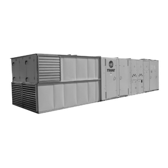
- Page 1 Installation Operation Maintenance Rooftop Energy Recovery Module TKD / TKH / WKD / WKH YKD / YKH / DKD / DKH # 125-155-175-200–250–265-290-340 # 275-300-350-400-500-600 RT-SVX42B-E4 April 2011...
-
Page 2: General Information
The consignee (or the site representative) and for air flow temperature between technician should be employed through the must notify your local Trane sales office -20°C and +40°C. Different conditions medium of a maintenance contract with and send a copy of the delivery note. The need written confirmation from the a reputable service company. -
Page 3: Table Of Contents
Contents General Information Cable preparation Exhaust / Return fan cable connection Service Test Guide for Component Operation Exhaust fan setup Free cooling operation Defrost pressure switch (PHE version) Appendix RT-SVX42B-E4... - Page 4 Installation Energy Recovery Module Cut the cable tie and prepare the cables at the border of the ERM to ease the cable (ERM) preparation installation into the rooftop front side. Use the provided gasket inside the rooftop Mount and use the delivered lifting device unit and fix it to the ERM internal edge as for ERM handling as shown in Figure 2.
- Page 5 Installation The ERM needs to be supported on the perimeter panels. The frame surface should be flat and perfectly aligned with the rooftop bottom plan. Position the ERM so that it is aligned with the down left corner of the rooftop. See Figure 3. Figure 3 - Fasten the ERM with the flat / back side flange (1) to ensure the ERM is perfectly aligned with the rooftop.
- Page 6 Installation Fasten the roof end to the ERM with self-drilling screws as shown in Figure 5. Figure 5a - Figure 5b - Run all the ERM cable (power and actuator) and transparent hose (if installed) into the rooftop fresh air / filter section. Place the fresh air filter into the filter rack located behind the fresh air inlet louver of the ERM.
-
Page 7: Cable Preparation
Installation Cable preparation Depending on the ERM type and rooftop size, different connections need to be made. Refer to Figure 6 to perform the necessary connections. Figure 6 - Connections 125-155-175-200-250-265-290-340 125-155-175-200-250-265-290-340 R’ 275-300-350-400-500-600 275-300-350-400-500-600 Plastic hose - Defrost pressure switch negative pressure port Plastic hose - Defrost pressure switch positive pressure port Power cable –... -
Page 8: Exhaust / Return Fan Cable Connection
Installation Exhaust / Return fan cable Figure 7 - connection Run the power exhaust fan motor power cables to the speed inverter. Connect the three phases and ground cable(s) to the MOTOR terminal of the speed inverter. Respect the cable numbers as shown in Figure 7. - Page 9 Installation On unit sizes 125-155-175-200-250- 265-290-340, the return air sensor of the economizer needs to be placed into to return air section of the ERM. Place return air temperature sensors in the air return section of the ERM as indicated in Figure 9.
-
Page 10: Service Test Guide For Component Operation
Operation Service Test Guide for Component Operation Test and setup of the ERM is performed during the first two steps of the rooftop test sequence. Step 1 of the test simulates normal ventilation mode of the unit. Step 2 of the test simulates free cooling mode. During step 1, adjust the return air damper position by turning the minimum position potentiometer on the Economizer module (ECA). - Page 11 Operation Figure 10b - Air circulation in normal operation 125-155-175-200-250-265-290-340 125-155-175-200-250-265-290-340 Min% Min% Min% Min% Min% 100% Min% M M M M i i i 100-Min% 100% Min% Min% Min% 100% 100% 100% 275-300-350-400-500-600 275-300-350-400-500-600 open 100% Min% Min% Min% Min% Min% 100-Min%...
-
Page 12: Exhaust Fan Setup
Operation Exhaust fan setup Free cooling operation In case of dual exhaust fan, set up both Free cooling is controlled by Reliatel ECA exhaust fan inverters at the same reference. board. When free cooling is enabled, mix return air damper will close and energy Adjust the minimum speed (x% fresh recovery heat exchanger will be deactivated. - Page 13 Operation Figure 12 - Air circulation in free cooling operation 125-155-175-200-250-265-290-340 125-155-175-200-250-265-290-340 100% 100% 100% 100% 100% 100% 100% 100% 100% 100% 100% By-pass 100% 100% 100% 275-300-350-400-500-600 275-300-350-400-500-600 Closed 100% 100% 100% 100% 100% 100% 100% 100% 100% 100% 100% 100% By-pass...
-
Page 14: Defrost Pressure Switch (Phe Version)
Operation Defrost pressure switch (PHE version) In winter mode, frost occurs in the return air side of the exchanger increasing pressure drop. The defrost pressure switch setting should be setup so that it does not switch in free cooling mode (100% exhaust air flow). During the free cooling test mode, adjust the pressure switch setting to reach the threshold point. -
Page 15: Appendix
Appendix Table 1 - Exhaust fan performances Downflow Plate Heat Exchanger (PHE - D) 50 Pa 150 Pa 250 Pa 350 Pa Airflow Inverter Inverter Inverter Inverter Unit size absorbed kW Fan speed absorbed kW Fan speed absorbed kW Fan speed absorbed kW Fan speed m3/h... - Page 16 Appendix Downflow Plate Heat Exchanger (PHE - D) 50 Pa 150 Pa 250 Pa 350 Pa Airflow Inverter Inverter Inverter Inverter Unit size absorbed kW Fan speed absorbed kW Fan speed absorbed kW Fan speed absorbed kW Fan speed m3/h setting setting setting...
- Page 17 Appendix Table 2 - Exhaust fan performances Horizontal flow Plate Heat Exchanger (PHE - H) 50 Pa 150 Pa 250 Pa 350 Pa Airflow Inverter Inverter Inverter Inverter Unit size absorbed kW Fan speed absorbed kW Fan speed absorbed kW Fan speed absorbed kW Fan speed...
- Page 18 Appendix Horizontal flow Plate Heat Exchanger (PHE - H) 50 Pa 150 Pa 250 Pa 350 Pa Airflow Inverter Inverter Inverter Inverter Unit size absorbed kW Fan speed absorbed kW Fan speed absorbed kW Fan speed absorbed kW Fan speed m3/h setting setting...
- Page 19 Appendix Table 3 - Exhaust fan performances Downflow Energy Recovery Wheel (ERW - D) 50 Pa 150 Pa 250 Pa 350 Pa Airflow Inverter Inverter Inverter Inverter Unit size absorbed kW Fan speed absorbed kW Fan speed absorbed kW Fan speed absorbed kW Fan speed m3/h...
- Page 20 Appendix Downflow Energy Recovery Wheel (ERW - D) 50 Pa 150 Pa 250 Pa 350 Pa Airflow Inverter Inverter Inverter Inverter Unit size absorbed kW Fan speed absorbed kW Fan speed absorbed kW Fan speed absorbed kW Fan speed m3/h setting setting setting...
- Page 21 Appendix Table 4 - Exhaust fan performances Horizontal flow Energy Recovery Wheel (ERW - H) 50 Pa 150 Pa 250 Pa 350 Pa Airflow Inverter Inverter Inverter Inverter Unit size absorbed kW Fan speed absorbed kW Fan speed absorbed kW Fan speed absorbed kW Fan speed...
- Page 22 Appendix Horizontal flow Energy Recovery Wheel (ERW - H) 50 Pa 150 Pa 250 Pa 350 Pa «Airflow Inverter Inverter Inverter Inverter Unit size absorbed kW Fan speed absorbed kW Fan speed absorbed kW Fan speed absorbed kW Fan speed m3/h»...
- Page 23 Notes RT-SVX42B-E4...
- Page 24 HVAC systems, comprehensive building services, and parts. For more information, visit www.Trane.com. Trane has a policy of continuous product and product data improvement and reserves the right to change design and specifications without notice.
Need help?
Do you have a question about the TKD and is the answer not in the manual?
Questions and answers