
Related Manuals for ZyXEL Communications ES-1100


Summary of Contents for ZyXEL Communications ES-1100
- Page 1 ES1100 Series 8/16/24 Port Unmanaged Fast Ethernet Switch Version 1.00 Edition 2, 4/2011 www.zyxel.com www.zyxel.com Copyright © 2011 ZyXEL Communications Corporation...
-
Page 3: About This User's Guide
Customer Support Should problems arise that cannot be solved by the methods listed above, you should contact your vendor. If you cannot contact your vendor, then contact a ZyXEL office for the region in which you bought the device. ES1100 Series User’s Guide... - Page 4 About This User's Guide See http://www.zyxel.com/web/contact_us.php for contact information. Please have the following information ready when you contact an office. • Product model and serial number. • Warranty Information. • Date that you received your device. • Brief description of the problem and the steps you took to solve it.
-
Page 5: Document Conventions
Document Conventions Document Conventions Warnings and Notes These are how warnings and notes are shown in this User’s Guide. Warnings tell you about things that could harm you or your device. Note: Notes tell you other important information (for example, other things you may need to configure or helpful tips) or recommendations. -
Page 6: Safety Warnings
Safety Warnings Safety Warnings • Do NOT use this product near water, for example, in a wet basement or near a swimming pool. • Do NOT expose your device to dampness, dust or corrosive liquids. • Do NOT store things on the device. •... -
Page 7: Table Of Contents
Table of Contents Table of Contents About This User's Guide ......................3 Document Conventions ......................5 Safety Warnings........................6 Table of Contents ........................7 Chapter 1 Getting to Know Your Switch....................9 1.1 Overview ..........................9 1.2 Features ..........................10 1.3 Applications .......................... 11 1.3.1 Standalone Workgroup .................... - Page 8 Table of Contents ES1100 Series User’s Guide...
-
Page 9: Getting To Know Your Switch
H A PT ER Getting to Know Your Switch 1.1 Overview This User’s Guide covers the following models: ES1100-16, ES1100-24, ES1100-24E, ES1100-8P, and ES1100-16P. The Switch can be used to build high-performance switched workgroup networks. The following table lists features that are specific to individual models: Table 1 ES1100 Series Comparison Table MODEL FEATURE ES1100-8P... -
Page 10: Features
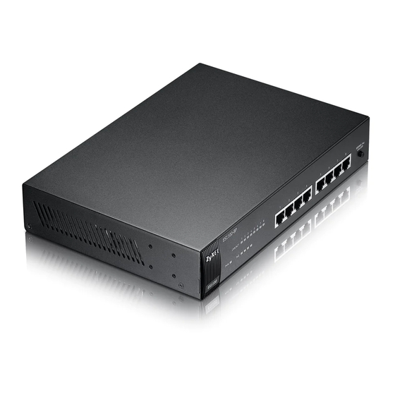
Chapter 1 Getting to Know Your Switch Figure 1 Front Panel ES1100-8P ES1100-16 ES1100-16P ES1100-24E ES1100-24 The Switch has a built-in algorithm that automatically assigns priority to received packets. 1.2 Features The following are the essential features of the Switch. •... -
Page 11: Applications
Chapter 1 Getting to Know Your Switch • Link-on cable length power saving and link-down power saving. • IEEE 802.3az (only ES1100-16/24E/24) • Loop detection (only ES1100-16/24E/24) • Jumbo frame (only ES1100-16/24E/24) • Embedded MAC address table providing MAC addresses entries (ES1100-16, ES1100-16P, ES1100-24 and ES1100-24E provide 8K;... -
Page 12: Power Over Ethernet (Poe)
Chapter 1 Getting to Know Your Switch The following figure depicts a typical segment bridge application of the Switch in an enterprise environment. The two networks (RD and Sales), the standalone server and the computers can all communicate with each other and share all network resources. Figure 3 Bridging Example 1.4 Power Over Ethernet (PoE) The PoE function is available for ES1100-8P and ES1100-16P only. -
Page 13: Hardware Description And Connection
H A PT ER Hardware Description and Connection 2.1 Rear Panel The three-pronged power receptacle is located on the rear panel of the Switch. Refer to the Product Specifications on page 23 for power specification. Figure 5 Rear Panel ES1100-8P ES1100-16 ES1100-16P ES1100-24E... -
Page 14: Front Panel
Chapter 2 Hardware Description and Connection For ES1100-16/24E, use the ON/OFF switch to have the Switch power on or off. 2.2 Front Panel The front panel of the Switch includes the auto-negotiating 10 Base-T/100 Base-TX RJ-45 ports and the LEDs. 2.2.1 RJ-45 Auto-negotiating Ports The 10 Base-T/100 Base-TX RJ-45 ports are auto-negotiating and auto-crossover. -
Page 15: Front Panel Leds
Chapter 2 Hardware Description and Connection 2.2.3 Front Panel LEDs The LED Indicators give real-time information about the status of the Switch. The following tables provide descriptions of the LEDs. Figure 6 LEDs for ES1100-16/24/24E ES1100-16 ES1100-24 ES1100-24E Table 3 LED Descriptions for ES1100-16/24/24E COLOR STATUS DESCRIPTION... -
Page 16: Hardware Installation
Chapter 2 Hardware Description and Connection 2.3 Hardware Installation See the following table for a comparison of the hardware installation methods of each ES1100 model: Table 5 ES1100 Series Installation Comparison Table MODEL FEATURE ES1100-8P ES1100-16 ES1100-16P ES1100-24 ES1100-24E Desktop Device Wall-mountable Rack-mountable Note: Ask an authorized technician to attach the Switch to the rack/wall. -
Page 17: Rack Mounting
Chapter 2 Hardware Description and Connection Align the holes on the back of the Switch with the screws on the wall. Hang the Switch on the screws. The Switch should be wall-mounted horizontally. The Switch's side panels with ventilation slots should not be facing up or down as this position is less safe. - Page 18 Chapter 2 Hardware Description and Connection Attaching the Mounting Brackets to the Switch Position a mounting bracket on one side of the Switch, lining up the four screw holes on the bracket with the screw holes on the side of the Switch. Figure 8 Attaching the Mounting Brackets (ES1100-8P/16/16P/24E) Figure 9 Attaching the Mounting Brackets (ES1100-24) Using a #2 Philips screwdriver, install the M3 flat head screws through the mounting bracket holes...
-
Page 19: Mounting The Switch On A Rack
Chapter 2 Hardware Description and Connection 2.3.3 Mounting the Switch on a Rack Position a mounting bracket (that is already attached to the Switch) on one side of the rack, lining up the two screw holes on the bracket with the screw holes on the side of the rack. Figure 10 Mounting the Switch on a Rack (ES1100-8P/16/16P/24E) Figure 11 Mounting the Switch on a Rack (ES1100-24) Using a #2 Philips screwdriver, install the M5 flat head screws through the mounting bracket holes... -
Page 20: Chapter 3 Troubleshooting
H A PT ER Troubleshooting This section describes common problems you may encounter with the Switch and possible solutions. Troubleshoot the Switch using the LEDs to detect problems. The PWR LED on the front panel does not light up. • Check the connections from your Switch to the power source. Make sure you are using the supplied power cord and that you are using an appropriate power source. -
Page 21: Improper Network Cabling And Topology
Chapter 3 Troubleshooting 3.1 Improper Network Cabling and Topology Improper network cabling or topology setup is a common cause of poor network performance or even network failure. Figure 12 Troubleshooting Improper Network Cabling and Topology PROBLEM CORRECTIVE ACTION Faulty cables Using faulty network cables may affect data rates and have an impact on your network performance. - Page 22 Chapter 3 Troubleshooting ES1100 Series User’s Guide...
-
Page 23: Product Specifications
H A PT ER Product Specifications These are the product specifications. Table 6 Product Specifications Dimension ES1100-8P/16P: 262mm(W) x 184mm(D) x 41mm(H) ES1100-16: 216 mm (W) x 133 mm (D) x 42 mm (H) ES1100-24: 441 mm (W) x 131 mm (D) x 44 mm (H) ES1100-24E: 267 mm (W) x 162 mm (D) x 42 mm (H) Weight ES1100-8P: 1.4 kg... -
Page 24: Chapter 4 Product Specifications
Chapter 4 Product Specifications Table 6 Product Specifications (continued) Memory ES1100-8P: 1K MAC entries, 96 K bytes buffer Memory ES1100-16/24/24E: 8K MAC entries, 256 K bytes buffer Memory ES1100-16P: 8K MAC entries, 160 K bytes buffer Memory Jumbo Frame Up to 2048 bytes (for ES1100-16/24/24E) Operating 0 ~ 50 Temperature... -
Page 25: Appendix A Legal Information
Published by ZyXEL Communications Corporation. All rights reserved. Disclaimer ZyXEL does not assume any liability arising out of the application or use of any products, or software described herein. Neither does it convey any license under its patent rights nor the patent rights of others. - Page 26 ZyXEL. This warranty shall not apply if the product has been modified, misused, tampered with, damaged by an act of God, or subjected to abnormal working conditions.
-
Page 27: Index
Index Index Applications LED Descriptions Segment Bridge LK/ACT auto-negotiating ports mounting brackets Cabling Length certifications notices viewing copyright network cable crossover straight-through Network Cable Types Non-standard network cables Data path loop disclaimer product registration Product specification Faulty cables FCC interference statement Front Panel Front Panel Connections rack mounting... - Page 28 Index Standalone Workgroup syntax conventions Troubleshooting Improper Network Cabling and Topology wall mounting warranty note ES1100 Series User’s Guide...
- Page 29 Index ES1100 Series User’s Guide...
- Page 30 Index ES1100 Series User’s Guide...
Need help?
Do you have a question about the ES-1100 and is the answer not in the manual?
Questions and answers