Advertisement
Quick Links
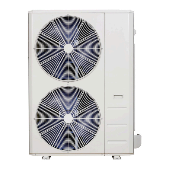
Outdoor Unit Single Zone Ductless System
Sizes 36 to 58
Fig. 1 —Size 36K
Fig. 2 —Sizes 48K - 58K
NOTES: Read the entire instruction manual before
starting the installation.
Images are for illustration purposes only. Actual
models may differ slightly.
Installation Instructions
Specifications subject to change without notice.
TABLE OF CONTENTS
SAFETY CONSIDERATIONS . . . . . . . . . . . . . . . . . . . . . . . . . . . . . 2
INTRODUCTION . . . . . . . . . . . . . . . . . . . . . . . . . . . . . . . . . . . . . . . 3
ACCESSORIES . . . . . . . . . . . . . . . . . . . . . . . . . . . . . . . . . . . . . . . . . 3
DIMENSIONS . . . . . . . . . . . . . . . . . . . . . . . . . . . . . . . . . . . . . . . . . . 4
CLEARANCES . . . . . . . . . . . . . . . . . . . . . . . . . . . . . . . . . . . . . . . . . 6
INSTALLATION REQUIREMENTS . . . . . . . . . . . . . . . . . . . . . . . . 7
INSTALLATION . . . . . . . . . . . . . . . . . . . . . . . . . . . . . . . . . . . . . . . . 7
Step 1 - Check Equipment . . . . . . . . . . . . . . . . . . . . . . . . . . . . . . . . . 7
Step 2 - Mount Unit . . . . . . . . . . . . . . . . . . . . . . . . . . . . . . . . . . . . . . 7
Step 3 - Condensate Drain Installation . . . . . . . . . . . . . . . . . . . . . . . . 8
Step 4 - Refrigerant Piping . . . . . . . . . . . . . . . . . . . . . . . . . . . . . . . . . 9
Step 5 - Evacuate Coil And Tubing System . . . . . . . . . . . . . . . . . . . 12
Step 6 - Electrical Connections. . . . . . . . . . . . . . . . . . . . . . . . . . . . . 13
WIRING . . . . . . . . . . . . . . . . . . . . . . . . . . . . . . . . . . . . . . . . . . . . . . 13
ELECTRICAL DATA . . . . . . . . . . . . . . . . . . . . . . . . . . . . . . . . . . . 14
CONNECTION DIAGRAMS . . . . . . . . . . . . . . . . . . . . . . . . . . . . . 14
START-UP . . . . . . . . . . . . . . . . . . . . . . . . . . . . . . . . . . . . . . . . . . . . 15
CARE AND MAINTENANCE . . . . . . . . . . . . . . . . . . . . . . . . . . . . 15
OUTDOOR UNIT DIAGNOSTIC GUIDES . . . . . . . . . . . . . . . . . . 15
DUCTLESS START-UP CHECKLIST . . . . . . . . . . . . . . . . . . . . . . 16
Page
Advertisement

Subscribe to Our Youtube Channel
Related Manuals for Carrier 38MBRCQ58AA3


Summary of Contents for Carrier 38MBRCQ58AA3
- Page 1 Outdoor Unit Single Zone Ductless System Sizes 36 to 58 Installation Instructions TABLE OF CONTENTS Page SAFETY CONSIDERATIONS ......2 INTRODUCTION .
- Page 2 38MBRC: Installation Instructions SAFETY CONSIDERATIONS WARNING Installing, starting up, and servicing air- conditioning equipment can be hazardous due to system pressures, electrical components, and equipment location (roofs, elevated structures, etc.). ELECTRICAL SHOCK HAZARD Only trained, qualified installers and service mechanics should install, Failure to follow this warning could result in personal injury or start- up, and service this equipment.
- Page 3 VOLTAGE - SYSTEM TONS kBTUh OUTDOOR MODEL PHASE 36,000 208/230 - 1 38MBRCQ36AA3 48,000 208/230 - 1 38MBRCQ48AA3 58, 000 208/230 - 1 38MBRCQ58AA3 Manufacturer reserves the right to change, at any time, specifications and designs without notice and without obligations.
- Page 4 38MBRC: Installation Instructions DIMENSIONS Table 3 — Dimensions UNIT SIZE Height in (mm) 31.89 (810) 52.48 (1333) 52.48 (1333) Width in (mm) 37.24 (946) 37.48 (952) 37.48 (952) Depth in (mm) 16.14 (410) 16.34 (415) 16.34 (415) Operating Weight lbs (kg) 155.42 (70.5) 219.14 (99.4) 217.15 (98.5)
- Page 5 38MBRC: Installation Instructions DIMENSIONS (CONT.) Sizes 48K - 58K Fig. 5 —Sizes 48K - 58K Manufacturer reserves the right to change, at any time, specifications and designs without notice and without obligations.
- Page 6 38MBRC: Installation Instructions CLEARANCES Air inlet Air outlet Fig. 6 — Outdoor Unit Clearances Table 4 — Outdoor Unit Clearance Dimensions MINIMUM VALUE UNIT in. (mm) 24 (610) 24 (610) 24 (610) 4 (101) 4 (101) 19in (48cm) or more on a multiple parallel unit arrangement 4in (10cm) or more on a single...
- Page 7 38MBRC: Installation Instructions INSTALLATION REQUIREMENTS INSTALLATION • A location which is convenient to installation and not exposed to strong Step 1 - Check Equipment winds. Unpack the unit and move to the final location. Remove the carton, taking • A location which can bear the weight of the outdoor unit and where the care not to damage the unit.
- Page 8 Per Unit 38MBRCQ36AA3 12600801A00117 Seal 38MBRCQ48AA3 12600801A00118 38MBRCQ58AA3 Drain Base pan joint Fig. 9 —Drain Joint NOTE: Images are for illustration purposes only. Manufacturer reserves the right to change, at any time, specifications and designs without notice and without obligations.
- Page 9 38MBRC: Installation Instructions Step 4 - Refrigerant Piping Table 6 — Piping and Refrigerant Information SYSTEM SIZE Min. Piping Length ft (m) 10(3) 10(3) 9.8 (3) Standard Piping Length ft (m) 25(7.5) 25(7.5) 24.6 (7.5) Max. outdoor-indoor height difference (OU higher than IU) ft (m) 98(30) 98(30)
- Page 10 38MBRC: Installation Instructions Use the following steps to connect the refrigerant piping: 5. Flare Pipe Ends 1. Run the interconnecting piping from the outdoor unit to the indoor Proper flaring is essential to achieving an airtight seal. unit. a. After removing the burrs from the cut pipe, seal the ends with PVC 2.
- Page 11 38MBRC: Installation Instructions 6. Connect the Pipes Connect the copper pipes to the indoor unit first, then connect the All tubing bends should be performed with a properly sized tubing bender pipes to the outdoor unit. Connect the low-pressure pipe first, then to prevent kinking or damaging the tubing.
- Page 12 38MBRC: Installation Instructions Step 5 - Evacuate Coil And Tubing System Evacuation Evacuation of the system will remove air or nitrogen (non-condensables) as CAUTION well as moisture. A proper vacuum will assure a tight, dry system before charging with refrigerant. The two methods used to evacuate a system are the deep vacuum method and the triple vacuum method.
- Page 13 38MBRC: Installation Instructions Step 6 - Electrical Connections WIRING Install All Power and Interconnecting Wiring to All wires must be sized per NEC (National Electrical Code) or CEC (Canadian Electrical Code) and local codes. Use Electrical Data table MCA (minimum Outdoor Units circuit amps) and MOCP (maximum over current protection) to correctly size 1.
- Page 14 38MBRC: Installation Instructions ELECTRICAL DATA Table 9 — Electrical Data OUTDOOR UNIT SIZE 208/230 - 1 - 60 208/230 - 1 - 60 208/230 - 1 - 60 Max – Min* Oper. Voltage 253 - 187 253 - 187 253 - 187 Power Supply MOCP Volts- PH- Hz...
- Page 15 38MBRC: Installation Instructions START-UP Outdoor Unit Are there unusual noises or vibrations during operation? Test Operation Explain the Following Item to the Customer (with the aid of Perform a test operation after completing a gas leak and electrical safety the Owner's Manual): check.
- Page 16 38MBRC: Installation Instructions DUCTLESS START-UP CHECKLIST Installation Data Site Address:_______________________________________________________________________________________________________ City:________________________________________________________ State:___________ Zip Code:__________________ Installing Contractor:______________________________________________________ Contractor Contact #: ( ) _____-___________ Job Name:_______________________________________________________________ Start-up Date:_____________________________ Distributor:_______________________________________________________________ System Details Units Model No. Serial No. Controller OUTDOOR UNIT INDOOR UNIT A Wiring Electrical Wire Size and Type Used? AWG:__________ TYPE:_________ Are there any breaks, splices, wire nuts or butt connectors between the outdoor unit and the indoor door unit?
- Page 17 38MBRC: Installation Instructions Ductless Start-Up Checklist (CONT) Piping Leak Check: System held 500 psig (max. 550psi) for a minimum of 30 minutes using dry nitrogen. YES:______ NO:______ Evacuation Method: • YES:______ NO:______ Was the Triple Evacuation Method used as outlined in the installation manual? •...
- Page 18 38MBRC: Installation Instructions © 2022 Carrier. All rights reserved. Edition Date: 04/22 Catalog No: 38MBRC-01SI Replaces: NEW Manufacturer reserves the right to change, at any time, specifications and designs without notice and without obligations.
Need help?
Do you have a question about the 38MBRCQ58AA3 and is the answer not in the manual?
Questions and answers