Table of Contents
Advertisement
Quick Links
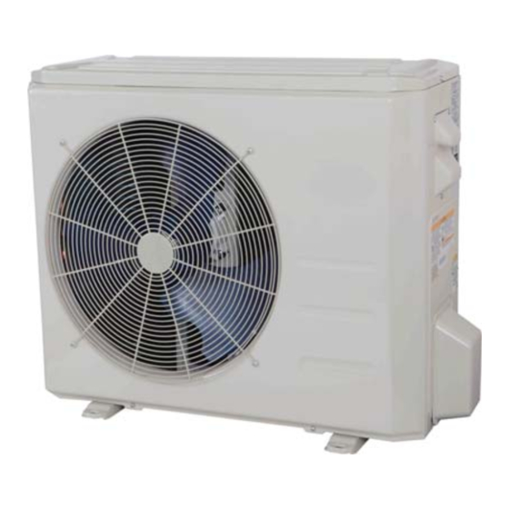
38MPRA
Outdoor Unit Single Zone Ductless System
Sizes 09 to 12
NOTES:
Read the entire instruction manual before starting the
installation.
Images are for illustration purposes only. Actual models
may differ slightly.
Installation Instructions
TABLE OF CONTENTS
. . . . . . . . . . . . . . . . . . . . . . . . . . . . . . . . . . . . . . .
. . . . . . . . . . . . . . . . . . . . . . . . . . . . . . . . . . . . . . . . . . .
. . . . . . . . . . . . . . . . . . . . . . . . . . . . . . . .
. . . . . . . . . . . . . . . . . . . . . . . . . . . . . . . .
. . . . . . . . . . . . . . . . . . . . . . . . . . . . . . . . . . . . . . . .
. . . . . . . . . . . . . . . . . . . . . . . . .
. . . . . . . . . . . . . . . . . . . . . . . . . . .
. . . . . . . . . . . . . . . . . . . . . . . . . .
. . . . . . . . . . . . . . . . . . . . . . . . .
. . . . . . . . . . . . . . . . . . . . .
. . . . . . . . . . . . . . . . . . . . . . . . . . .
. . . . . . . . . . . . . . . . . . .
. . . . . . . . . . . . . .
PAGE
2
3
4
4
5
6
7
7
9
9
10
11
11
Advertisement
Table of Contents

Related Manuals for Carrier 38MPRA


Summary of Contents for Carrier 38MPRA
-
Page 1: Table Of Contents
38MPRA Outdoor Unit Single Zone Ductless System Sizes 09 to 12 Installation Instructions TABLE OF CONTENTS PAGE SAFETY CONSIDERATIONS ...... -
Page 2: Safety Considerations
SAFETY CONSIDERATIONS WARNING Installing, starting up, and servicing air−conditioning equipment can be hazardous due to system pressures, electrical components, ELECTRICAL SHOCK HAZARD and equipment location (roofs, elevated structures, etc.). Failure to follow this warning could result in personal Only trained, qualified installers and service mechanics should injury or death. -
Page 3: Parts List
PARTS LIST Table 1—Parts List PART NO. PART NAME QTY. Outdoor unit Literature package including installation instructions and warranty Grommet to secure the outdoor unit (helps with vibration prevention during unit operation) Drain Joint Drain Hose ■ Outdoor A150766 Fig. 1 - Parts List NOTE: −... -
Page 4: System Requirements
SYSTEM REQUIREMENTS Allow sufficient space for airflow and service of the unit. See Fig. 3 for the required minimum distances between the unit, walls or ceilings. Piping IMPORTANT: Both refrigerant lines must be insulated separately. S Table 3 contains piping information for the product covered within this document. Table 3—Piping and Refrigerant Information System Size 9K (208-230V) -
Page 5: Dimensions − Outdoor
DIMENSIONS − OUTDOOR Table 4—Dimensions and Weights System Size Height (H) in. (mm) Width (W) in. (mm) Depth (D) in. (mm) Weight-Net lbs. (kg) (208/230V) 27.64(702) 33.27(845) 14.29(363) 107.59(48.8) (208/230V) 27.64(702) 33.27(845) 14.29(363) 108.47(49.2) Fig. 2 - Sizes 9K and 12K... -
Page 6: Clearances − Outdoor
CLEARANCES − OUTDOOR Air-inlet Air-outlet Fig. 3 - Outdoor Unit Clearance Table 5—Outdoor Unit Clearance Dimensions UNIT MINIMUM VALUE in. (mm) 24 (610) 24 (610) 24 (610) 4 (101) 4 (101) NOTE: The outdoor unit must be mounted at least 2in. (50mm) above the maximum anticipated snow depth. Fig. -
Page 7: Installation Tips
INSTALLATION TIPS Ideal installation locations include: 4. Remove all the burrs from the cut cross section of the pipe avoiding any burrs inside the tubes. Outdoor Unit S A location which is convenient to installation and not exposed to 5. Remove the flare nuts attached to the indoor and outdoor units. - Page 8 INSTALL ALL POWER AND INTERCONNECTING DRAIN CONNECTIONS WIRING TO OUTDOOR UNITS Install drains must meet local sanitation codes. 1. Mount the outdoor power disconnect. Install the outdoor unit drain joint 2. Run the power wiring from the main box to disconnect per Fit the seal into the drain joint, then insert the drain joint into the NEC and local codes.
-
Page 9: Electrical Data
ELECTRICAL DATA Table 9—Electrical Data (Heat Pump) Outdoor Unit Size Volts-PH-Hz (208/230V) (208/230V) Heat Pump Max – Min* 253-187 253-187 Oper. Voltage Power Supply MOCP Compressor Outdoor Fan Motor Rated HP 0.156 0.156 Output *Permissible limits of the voltage range at which the unit will operate satisfactorily. LEGEND FLA - Full Load Amps MCA - Minimum Circuit Amps... -
Page 10: System Vacuum And Charge
SYSTEM VACUUM AND CHARGE Deep Vacuum Method CAUTION The deep vacuum method requires a vacuum pump capable of pulling a vacuum of 500 microns and a vacuum gage capable of accurately measuring this vacuum depth. The deep vacuum method is the best UNIT DAMAGE HAZARD way to assure a system is free of air and liquid water (see Fig. -
Page 11: Start−Up
START−UP Test Operation OUTDOOR UNIT Perform a test operation after completing a gas leak and electrical Are there unusual noises or vibrations during operation? safety check. See the indoor unit installation instructions and Explain the Following Items to the Customer (with the aid of owner’s manual for additional start up information. - Page 12 Copyright 2017 CAC/BDP . S 7310 W. Morris St. S Indianapolis, IN 46231 Edition Date: 8/17 Catalog No: IM-38MPRA-01 Replaces: NEW Manufacturer reserves the right to change, at any time, specifications and designs without notice and without obligations.
Need help?
Do you have a question about the 38MPRA and is the answer not in the manual?
Questions and answers