Table of Contents
Advertisement
38MG(R/H)B
Multi-zone Outdoor Unit Ductless System
Sizes 18R, 24HH, 30HH, 36R, 36HH, 48R and 48HH
Fig. 1 -Size 18K
Fig. 2 -Sizes 24KHH, 30KHH, and 36K
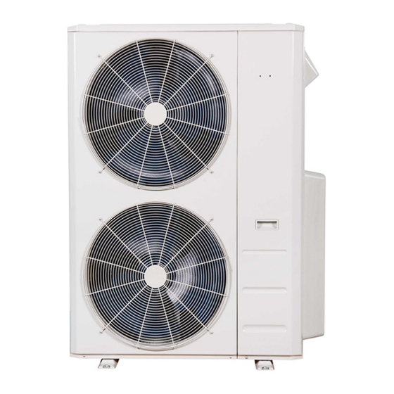
Fig. 3 -Sizes 36KHH, 48K, and 48KHH
NOTE: Read the entire instruction manual before starting the
installation.
Installation Instructions
AA220028
A220029
A220030
Specifications subject to change without notice.
TABLE OF CONTENTS
SAFETY CONSIDERATIONS . . . . . . . . . . . . . . . . . . . . . . . . . . . . . 2
GENERAL . . . . . . . . . . . . . . . . . . . . . . . . . . . . . . . . . . . . . . . . . . . . . 2
PARTS LIST . . . . . . . . . . . . . . . . . . . . . . . . . . . . . . . . . . . . . . . . . . . 3
SYSTEM REQUIREMENTS. . . . . . . . . . . . . . . . . . . . . . . . . . . . . . . 3
PIPING REQUIREMENTS . . . . . . . . . . . . . . . . . . . . . . . . . . . . . . . . 4
WIRING . . . . . . . . . . . . . . . . . . . . . . . . . . . . . . . . . . . . . . . . . . . . . . . 5
DIMENSIONS . . . . . . . . . . . . . . . . . . . . . . . . . . . . . . . . . . . . . . . . . . 6
CLEARANCES . . . . . . . . . . . . . . . . . . . . . . . . . . . . . . . . . . . . . . . . . 9
INSTALLATION GUIDE . . . . . . . . . . . . . . . . . . . . . . . . . . . . . . . . 10
OUTDOOR UNIT INSTALLATION . . . . . . . . . . . . . . . . . . . . . . . 10
ELECTRICAL DATA . . . . . . . . . . . . . . . . . . . . . . . . . . . . . . . . . . . 12
CONNECTION DIAGRAMS . . . . . . . . . . . . . . . . . . . . . . . . . . . . . 12
AUTOMATIC WIRING/PIPING CORRECTION . . . . . . . . . . . . . 15
SYSTEM VACUUM AND CHARGE. . . . . . . . . . . . . . . . . . . . . . . 16
START-UP . . . . . . . . . . . . . . . . . . . . . . . . . . . . . . . . . . . . . . . . . . . . 17
OUTDOOR UNIT DIAGNOSTIC GUIDES . . . . . . . . . . . . . . . . . . 18
Advertisement
Table of Contents

Related Manuals for Carrier 38MG BQ Series


Summary of Contents for Carrier 38MG BQ Series
-
Page 1: Table Of Contents
38MG(R/H)B Multi-zone Outdoor Unit Ductless System Sizes 18R, 24HH, 30HH, 36R, 36HH, 48R and 48HH Installation Instructions TABLE OF CONTENTS SAFETY CONSIDERATIONS ......2 GENERAL . -
Page 2: Safety Considerations
38MGRBQ: Installation Instructions SAFETY CONSIDERATIONS WARNING SAFETY CONSIDERATIONS ......2 GENERAL ..........2 PARTS LIST. -
Page 3: Parts List
38MGRBQ: Installation Instructions PARTS LIST Table 1 — Parts List Part No. Part Name Outdoor Unit Literature package including installation instructions and warranty Vibration Pad Drain joint Conversion Joints (see Table 4) A22001 Fig. 4 —Parts List NOTES: - If the outdoor unit is higher than the indoor unit, prevent rain from flowing into the indoor unit along the connection pipe by making a downward arc in the connection pipe before it enters the wall to the indoor unit. -
Page 4: Piping Requirements
38MGRBQ: Installation Instructions PIPING REQUIREMENTS IMPORTANT: Both refrigerant lines must be insulated separately. The minimum refrigerant line length between the indoor and outdoor units is 10 ft. (3 m). The following lengths are allowed. Table 3 lists the pipe sizes for the outdoor unit. For the indoor unit pipe sizes refer to the indoor unit installation instructions. Table 3 —... -
Page 5: Wiring
38MGRBQ: Installation Instructions Table 5 — Additional Refrigerant Charge Min. No. Max. No. Additional Charge Additional Charge Total Maximum Unit Size Charge oz. Lbs (kg) of Zones of Zones Required After ft. (m) oz./ft. (g/m) Piping Length ft. (m.) 4.08(1.85) 49 (15) 0.16 (15) 131 (40) -
Page 6: Dimensions
38MGRBQ: Installation Instructions DIMENSIONS Table 6 — Dimensions 24K High Heat 30K High Heat 36K High Heat 48K High Heat System Size (208/230V) (208/230V) (208/230V) (208/230V) (208/230V) (208/230V) (208/230V) Height (H) 26.50(673) 31.89(810) 31.89(810) 31.89(810) 52.48(1333) 52.48(1333) 52.48(1333) (mm) Width (W) 35.04(890) 37.24(946) 37.24(946) - Page 7 38MGRBQ: Installation Instructions DIMENSIONS (CONT) 37-1/4 (946) 40-3/4 (1034) 3-1/4 26-1/2 (673) (81) DETAIL A SCALE 1:2 ø 0.5 (12) Dimensions: shown in inches (mm) A220004 Fig. 6 —Outdoor Dimensions Size 24K HH (High Heat) 3-1/4 37-1/4 (946) (81) 40-3/4 (1034) 26-1/2 (673) DETAIL A SCALE 1:2...
- Page 8 38MGRBQ: Installation Instructions 37.5 (952) W 16.3 (415) D 16.3 (415) D 8 (76.42) 41.7 (1060) W1 25 (634) A DETAIL A SCALE 1:2 DETAIL A SCALE 1:2 ø 0.5 (12) 2.9 (74) AA220010 Fig. 8 —Outdoor Dimensions Size 36K HH (High Heat), 48K, and 48K HH (High Heat) Manufacturer reserves the right to change, at any time, specifications and designs without notice and without obligations.
-
Page 9: Clearances
38MGRBQ: Installation Instructions CLEARANCES A220005 Fig. 9 — Clearances Table 7 — Clearance Values UNIT MINIMUM VALUE in. (mm) 24 (609) 24 (609) 24 (609) 4 (101) 6 (152) NOTE: The outdoor unit must be mounted at least 2in (50mm) above the maximum anticipated snow depth. A220006 Fig. -
Page 10: Installation Guide
38MGRBQ: Installation Instructions INSTALLATION GUIDE Piping Guide: • Do not open service valves or remove protective caps from tubing ends Up to five fan coil units can be connected to one outdoor unit. Refer to the until all the connections are made. product data for approved combinations. - Page 11 38MGRBQ: Installation Instructions 10. Connect both the liquid and gas piping to the indoor unit. 11. Tighten the flare nut using a torque wrench as specified in Table 9. 12. Complete the installation. Terminal block Table 9 — Tightening Torque Connecting cable Flare Dimension (A) Pipe...
-
Page 12: Electrical Data
38MGRBQ: Installation Instructions ELECTRICAL DATA Table 11 — Electrical Data SYSTEM VOLTAGE OPERATING VOLTAGE COMPRESSOR OUTDOOR FAN UNIT SIZE MOCP VOLT / PHASE / HZ MAX / MIN* 24 High Heat 0.16 24.5 30 High Heat 0.16 208/230/1/60 253/187 0.16 36 High Heat 0.11 0.11... - Page 13 38MGRBQ: Installation Instructions CONNECTION DIAGRAMS (CONT) A220015 Fig. 18 —Connection Diagram Size 24K 3 Zone High Heat A220016 Fig. 19 —Connection Diagram Size 30K 4 Zone High Heat Manufacturer reserves the right to change, at any time, specifications and designs without notice and without obligations.
- Page 14 38MGRBQ: Installation Instructions CONNECTION DIAGRAMS (CONT) A220017 Fig. 20 —Connection Diagram Size 36K 4 Zone (Standard and High Heat) A220018 Fig. 21 —Connection Diagram Size 48K 5 Zone (Standard and High Heat) Manufacturer reserves the right to change, at any time, specifications and designs without notice and without obligations.
-
Page 15: Automatic Wiring/Piping Correction
38MGRBQ: Installation Instructions AUTOMATIC WIRING/PIPING CORRECTION The unit is capable of automatically correcting a wiring/piping error. Indoor units do not have to be in the run mode. The outdoor temperature should ° ° C) to use this feature. Press SW1 on the outdoor unit PCB board for 6 seconds until the display shows “CE” (“FA” may appear first be above 41 F (5 –... -
Page 16: System Vacuum And Charge
38MGRBQ: Installation Instructions SYSTEM VACUUM AND CHARGE CAUTION UNIT DAMAGE HAZARD Failure to follow this caution may result in equipment damage or improper operation. Never use the system compressor as a vacuum pump. Refrigerant pipes and indoor unit coils should be evacuated using the recommended 500 microns deep vacuum method. -
Page 17: Start-Up
38MGRBQ: Installation Instructions A220026 Fig. 29 —Triple Evacuation Method Final Tubing Check A220024 Fig. 27 —Manifold Sizes 24-48 IMPORTANT: Ensure the factory tubing on both the indoor and outdoor unit has not shifted during shipment. Ensure Deep Vacuum Method tubes are not rubbing against each other or any sheet metal. The deep vacuum method requires a vacuum pump capable of Pay close attention to feeder tubes, making sure wire ties on the feeder tubes are secure and tight. -
Page 18: Outdoor Unit Diagnostic Guides
— — Communication malfunction between adapter board and outdoor main control board EL 16 — — © 2023 Carrier. All rights reserved. Edition Date: 04/23 Catalog No: IM-38MGRBQ-03 Replaces: IM-38MGRBQ-02 Manufacturer reserves the right to change, at any time, specifications and designs without notice and without obligations.
Need help?
Do you have a question about the 38MG BQ Series and is the answer not in the manual?
Questions and answers