Sign In
Upload
Download
Table of Contents
Contents
Add to my manuals
Delete from my manuals
Share
URL of this page:
HTML Link:
Bookmark this page
Add
Manual will be automatically added to "My Manuals"
Print this page
×
Bookmark added
×
Added to my manuals
Manuals
Brands
Toa Manuals
Speakers
F-03BT
Instruction manual
Toa F-03BT Instruction Manual
Speaker system
Hide thumbs
1
Table Of Contents
2
3
4
5
6
7
8
9
10
11
12
13
14
15
16
17
18
19
20
21
22
23
24
page
of
24
Go
/
24
Contents
Table of Contents
Bookmarks
Table of Contents
Table of Contents
Safety Precautions
Safety Symbol and Message Conventions
General Description and Features
Handling Precautions
Impedance Change
Dimensional Diagram
F-03Bt, F-03Wt
F-05Bt, F-05Wt
F-08Bt, F-08Wt
Speaker Cable Connections
Installation
Using the Supplied Brackets
Range of Speaker Installation Angle
Wall Mounting
Ceiling Mounting
Installation Examples Using the Optional Adapter Plates
Specifications
F-03Bt, F-03Wt
F-05Bt, F-05Wt
F-08Bt, F-08Wt
Advertisement
Quick Links
Download this manual
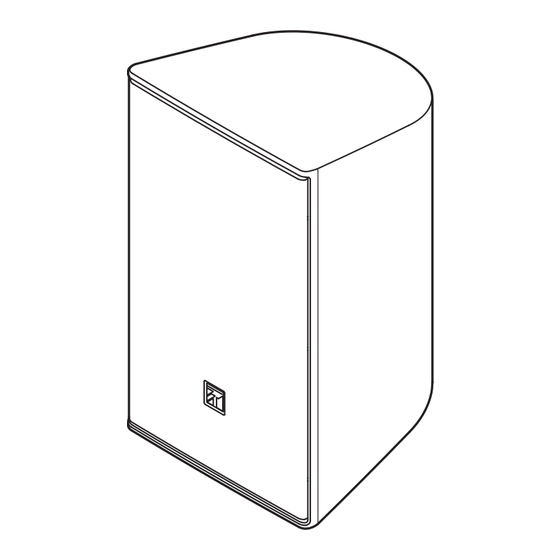
SPEAKER SYSTEM
F-03BT, F-03WT
Thank you for purchasing TOA's Speaker System.
Please carefully follow the instructions in this manual to ensure long, trouble-free use of your equipment.
F-05BT, F-05WT
INSTRUCTION MANUAL
F-03BT, F-03WT
F-05BT, F-05WT
F-08BT, F-08WT
F-08BT, F-08WT
Table of
Contents
Previous
Page
Next
Page
1
2
3
4
5
Advertisement
Table of Contents
Need help?
Do you have a question about the F-03BT and is the answer not in the manual?
Ask a question
Questions and answers
Related Manuals for Toa F-03BT
Speakers Toa F-03WT Instruction Manual
Speaker system (24 pages)
Speakers Toa F-05BT Instruction Manual
Speaker system (24 pages)
Speakers Toa F-05WT Instruction Manual
Speaker system (24 pages)
Speakers Toa F-08BT Instruction Manual
Speaker system (24 pages)
Speakers Toa F-08WT Instruction Manual
Speaker system (24 pages)
Speakers Toa F-03BT-WP-UE Instruction Manual
Speaker system (20 pages)
Speakers Toa F-122CU Specifications
F series (12 pages)
Speakers Toa BS-1030 Brochure
Toa bs-1030: supplementary guide (46 pages)
Speakers Toa F-2852CEN Instruction Manual
Ceiling speaker system (12 pages)
Speakers Toa F-160 Specification Sheet
Foreground music speakers (6 pages)
Speakers Toa F-160G Instruction Manual
F series speaker system (16 pages)
Speakers Toa F-240G Instruction Manual
F series speaker system (16 pages)
Speakers Toa F-240GM Instruction Manual
F series speaker system (16 pages)
Speakers Toa F-160W Instruction Manual
F series speaker system (16 pages)
Speakers Toa BS-1030 User Manual
Toa bs-1030: user guide (60 pages)
Speakers Toa F-2352C Instruction Manual
Ceiling speaker system (12 pages)
This manual is also suitable for:
F-03wt
F-05bt
F-05wt
F-08bt
F-08wt
Table of Contents
Print
Rename the bookmark
Delete bookmark?
Delete from my manuals?
Login
Sign In
OR
Sign in with Facebook
Sign in with Google
Upload manual
Upload from disk
Upload from URL


Need help?
Do you have a question about the F-03BT and is the answer not in the manual?
Questions and answers