
Related Manuals for Flexiheat BA-S Series


Summary of Contents for Flexiheat BA-S Series
- Page 1 TECHNICAL SPECIFICATIONS ASSEMBLY, USE AND MAINTENANCE INSTRUCTIONS VERTICAL WARM AIR HEATERS WITH CABINET RANGE BA-S...
-
Page 2: Pin Number
BA-S series. This User Manual includes important instructions and recommendations that should be complied with, in order to easily install and to better use the WARM AIR HEATER, BA-S series. Thank you, once again. - Page 3 INDEX GENERAL INFORMATION: Compliance Pin number Range Warranty Index General instruction Basic Safety rules Disposal Description Identification Structure of the warm air heater Net volume and weight Size of combustion chamber Technical data Product receipt INSTALLATION AND SETTINGS INSTRUCTIONS: Handling and transport Position Respect area Diffusion plenum...
-
Page 4: General Instructions
GENERAL INSTRUCTIONS This manual is an integral part of the machine, therefore it should always be carefully kept and it should always be provided together with the machine, if it is transferred to another owner or user. If this manual is damaged or lost, a new one should be asked to the local Technical Assistance Service or to the Producer. -
Page 5: Basic Safety Rules
BASIC SAFETY RULES Bear in mind that if you use products powered trough electric power, gas, etc., you should comply with some basic rules, such as: Children and non assisted disabled persons should not use the warm air heater. Electronic machines or devices, such as switches, household appliances, etc., should not be switched on if you smell fuel or non-burnt substances. - Page 6 DESCRIPTION The warm air heater is basically a thermal unit that exchanges the products resulting from the combustion of a forced draught burner for the air flow produced by a high-performing ventilation unit. The air to be heated is sucked by the ventilation unit and, when it laps the hot surface of the heat exchanger, it is heated - increasing its temperature;...
- Page 7 Smoke discharge inlet The machine is fitted with a round inlet where a metal pipe should be safely inserted and fixed, in order to discharge the combustion products. The smoke discharge system to be used should be compliant with all the relevant regulations and certified Diesel Tank The machine is fitted with a large capacity tank, with loading pipe coupling, filter and attachments for the...
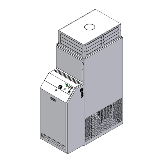
- Page 8 STRUCTURE OF THE WARM AIR HEATER Tank FAN thermostat Oil burner LIMIT thermostat Electrical board Electroventilator Chimney fitting Air outlet NET VOLUME AND WEIGHT VOLUME AND WEIGHT TABLE: TYPE A (mm) B (mm) C (mm) D (mm) Ø (mm) WEIGHT (kg) 1.050 1.600 1.175...
-
Page 9: Technical Date
SIZE OF COMBUSTION CHAMBER The heat exchanger has 3 smoke rings and the combustion chamber has the following size: TYPE A (mm) B (mm) C (mm) D (mm) ØE (mm) TECHNICAL DATE TYPE Thermal power 33,7 46,8 71,1 93,0 104,6 (burned) kcal/h 29.000... -
Page 10: Product Receipt
PRODUCT RECEIPT The warm air heater is supplied together with: Document envelope including: User guide Wiring diagram Warranty certificate Barcode tags HANDLING AND TRANSPORT The machine should be moved by properly equipped personnel and with devices fit for the machine weight. If a fork-lift is used, pitchfork the machine in the lower part using the appropriate ways in the wood bedplate. - Page 11 POSITION The installation site should be defined by the plant designer or by a competent person and it should take into account the technical needs as well as the relevant laws and regulations in force; specific authorizations are usually required. (e.g.: regulations concerning city planning, architecture, fire prevention, environmental pollution, noise level, etc.) Therefore, we suggest requesting and obtaining the relevant authorizations before installing the machine.
-
Page 12: Diffusion Plenum
Examples for installment: WARNING! Any law or specific regulations (e.g. fire prevention) shall be complied with. Consult the plant designer. DIFFUSION PLENUM The heater is equipped with a supply plenum with flaps. The regulation of the flaps must allow: a regular distribution of air ... -
Page 13: Fuel Line Connection
DUCTING It is possible, through canalization, to send part of the treated air volume in other places, through the pre-cut hole. Ø PRECUT HOLE (mm) Precut hole Connection with edge (not provided) Canalization (not provided) FUEL LINE CONNECTION The connection to the fuel line should be made by qualified and trained staff; carefully follow what written in the instruction manual for the burner and the current legislation. -
Page 14: Fixed Protections
FIXED PROTECTIONS To avoid accidental contact with any moving part of the heater it is absolutely forbidden to switch on the heater when it is not provided with its fixed protection which are: Burner inspection panel Back panel COMBURENT AIR The heater have to be installed according to the current legislation and used only in a place enough ventilated. -
Page 15: Control Board
WARNING ! Install a differential magnetothermal protection upstream of each equipment, according to current legislation. The equipment must always be connected to a plant with efficient earthing. Leave the earth cable a little longer than the line wires so that if they are accidentally pulled it is the last one to get detached. ... - Page 16 ELECTRICAL CHART LEGENDA: Voltage indicator Burner terminal board LIMIT indicator Burner Burner lock-out indicator Fan terminal board Heating / stop / fan switch Fan group Room thermostat Outside socket LIMIT thermostat IMT* Magnetic switch FAN thermostat *Outside the machine to be installed by the customer NOTE: the machine TYPE 1 and TYPE 2 are equipped with centrifugal fan with multi-speed motor directly coupled.
- Page 17 TANK The heater is equipped with a tank that not necessarily must be installed inside the heater (if the tank is positioned far away we can supply a closing panel) Closing panel Tank Filling the tank: Take off the burner panel; ...
- Page 18 REGULATING BURNER Burner assembly and setting should be carried out only by qualified and skilled personnel, carefully complying with the burner manual. NOTA BENE: The data specified below are only indicative. Adjustment of combustion air varies according to characteristics of chimney, and it should be made by acting on the shutter as described in the burner manual.
-
Page 19: Starting And Stopping
FUNCTIONING CYCLES WORKING THE FAN Follow these instructions to activate the fan: Connect the electricity to the unit Position the switch on the “fan” position In this condition only the fan works so the air exiting the heat is the same temperature of the air entering. WORKING THE HEATER Follow these instructions to activate the heater: ... - Page 20 Stopping: Stop the heater EXCLUSIVELY BY ACTING DIRECTLY ON THE ROOM THERMOSTAT by setting it at minimum temperature or opening the contact of the same switch (if present) or on STOP. Wait for fan stop ((~ 4 min.) and if necessary, power off by acting on general switch. Never stop the heather by operating the equipment off, as the heat energy accumulated in Exchanger, causes dangerous overheating situation in heat exchanger with possible damages to the heater.
- Page 21 FAN – LIMIT – SAFETY THERMOSTAT The sensor of these thermostats is placed on the warm air outlet and they have a double function: they start up and stop the ventilation unit (FAN function) and they safely stop the machine in case of overheating (LIMIT function).
-
Page 22: Maintenance
ENGINE ELECTRIC ABSORPTION MEASUREMENT OF THE ELECTRIC ENGINE ABSORPTION: In order to check the electric absorption of the fan engine, perform the following operations: insert the current clump on a wire of the general power line; set the machine on the summer ventilation mode, so as to exclude any other machine (burner and auxiliary devices);... -
Page 23: Limit Thermostat Maintenance
VENTILATION UNIT MAINTENANCE Periodically check the cleanliness of the fan assembly and take care particularly of cleaning the impeller. LIMIT THERMOSTAT MAINTENANCE Check that the LM safety thermostats properly work at least every 6 months. By manually rotating the graduated dial, simulate its activation and then check if the burner has gone off. Check that they are regularly restored when the unblock button is pushed. - Page 24 TYPE 4-5: remove the inspection panel 1. remove the inspection shutter 2. dismantle the burner 3. disconnect the chimney pipe from the connector 5. extract the reticular turbolators (if any) using the hook provided clean the pipe bundle elements 6 with a swab and remove smut and residual elements deposited in the combustion chamber, by using an extractor, though the burner opening 5.
-
Page 25: Customer Service
POSITION OF THE INLET FOR TAKING SMOKE SAMPLES In order to analyse the machine combustion, samples of combustion products should be taken in compliance with the following diagram: The trap for taking the samples of the combustions products is not provided together with the machine. CUSTOMER SERVICE The installation, commissioning and maintenance of the warm air heater shall be performed by qualified technical personnel. -
Page 26: Malfunctions, Causes And Remedies
MALFUNCTIONS, CAUSES AND REMEDIES MALFUNCTION PROBABLE CAUSE RECOMMENDED REMEDIES The burner does not start No power Check position of general power switch Check the line Check connections Check and turn to the heating Switch incorrectly positioned position The burner does not start: Excessive delivery of fuel Set to rating data The yellow light switch... - Page 27 The burner switches off when working regularly even when Faulty thermostat Replace the thermostat the room temperature is lower than the temperature set on the thermostat Replace or integrate with an appropriately rated appliance The thermal power of the heater is The heater operates insufficient to heat the environment continuously without reaching...
- Page 28 Since our Company is constantly committed to improve its products, their esthetical features, size, technical data, fittings, and additional devices might change. 12/15_Rev.05 281-GB-D...
Need help?
Do you have a question about the BA-S Series and is the answer not in the manual?
Questions and answers