
Related Manuals for Flexiheat ELIS B-W-100


Summary of Contents for Flexiheat ELIS B-W-100
- Page 1 ELIS B | W 100 | W 100 2R | N 100 | E 100 | W 150 | W 150 2R | N 150 | E 150 | W 200 | W 200 2R | N 200 | E 200 AIR CURTAIN TECHNICAL DOCUMENTATION OPERATION MANUAL ТЕХНИЧЕСКАЯ...
-
Page 2: Table Of Contents
TABLE OF CONTENTS 1. GENERAL INFORMATION ..............3 2. TECHNICAL DATA ................4 2.1. CONSTRUCTION ................4 2.2. DIMENSIONS ..................5 2.3. ACOUSTIC PRESSURE LEVEL/ ACOUSTIC POWER LEVEL ..5 2.4. AIR VOLUME ..................5 3. INSTALLATION ..................6 4. CONTROL SYSTEM ................8 4.1. -
Page 3: General Information
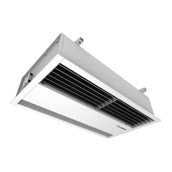
Elis B is a recessed type and can be a part suspended ceiling. ELiS types: ELIS B-W-100 – curtain with water heat exchanger max. range 5 m; ELIS B-N-100 – curtain without heat exchanger (ambient); max. range 5 m;... -
Page 4: Technical Data
2. TECHNICAL DATA B-W- B-N- B-E- B-W- B-W- B-N- B-E- B-W- B-W- B-N- B-E- B-W- 100 2R 150 2R 200 2R Power supply [V/Hz] | 3x400 230 / 3x400 230 / 3x400 230 / 230/ 50 230 / 50 230 / 50 / 50 / 50 / 50... -
Page 5: Dimensions
2.2. DIMENSIONS ELiS B-W/N/E/2R-100 1057 mm 600 mm 561 mm 770 mm 297*/284** mm 96 mm ELiS B-W/N/E/2R-150 1546 mm 600 mm 561 mm 1207 mm 297*/284** mm 84 mm ELiS B-W/N/E/2R-200 2034 mm 600 mm 561 mm 1621 mm 297*/284** mm 157 mm * height for B-W ;... -
Page 6: Installation
3. INSTALATION ELiS B [mm] A [mm] ELiS [mm] [mm] [mm] [mm] B-..-100 1024 B-..-100 B-..-150 1510 B-..-150 1207 B-..-200 2000 B-..-200 1621... -
Page 8: Control System
4. CONTROL SYSTEM DRV CONTROL: ▪ Connecting curtains – controlling up to 5 units with one controller; ▪ Connecting to curtain room thermostat*, door contact*, valves with actuator*, speed controller*; ▪ BMS connection; ▪ SYSTEM Flowair connection *optional equipment 4.1. CONTROL SYSTEM ELEMENTS TS - 3-speed fan switch with room thermostat Temperature range::... - Page 9 SRQ3d ½” – three-way 1/2 valve with actuator IP/Insulation class: IP20 Power supply: 200 – 240 V 50/60 Hz Max water temperature: Max water pressure: 2,1 MPa Kvs: 3,4 m Opening time: 18 s SRQ2d ½” – two-way 1/2 valve with actuator IP/Insulation class: IP20 Power supply: 200 –...
-
Page 10: Connecting Guide
4.2. CONNECTING GUIDE 7. ELiS B-W/N 8. ELiS B-E 10 |... -
Page 11: Drv Elis Control System
4.3. DRV ELiS CONTROL SYSTEM Power supply 230 V/50 Hz; Connectors for thermostat and fan step switch; Door contact connector; Valve actuator connector ELIS-…W; heaters contactor connector ELiS-…-E; BMS system connection; T-box connectors; MASTER-SLAVE connectors; ... -
Page 12: Regulation Ts-Elis B-W/N Wiring Diagrams
4.3.1. REGULATION TS-ELIS B-W/N WIRING DIAGRAMS Power supply 230 V/50 Hz (OMY 3x1 mm Air curtain step switch with thermostat TS (OMY 5x0,5mm • HEAT- heating mode • FAN - room thermostat deactivated • COOL - cooling mode •... -
Page 13: Regulation Ts-Elis B-E Wiring Diagrams
4.3.2. REGULATION TS-ELIS B-E WIRING DIAGRAMS Power supply 3x400V/50Hz • ELiS B-E-100 (min. 5x2,5 mm ) (Overcurrent B16) • ELiS B-E-150 (min. 5x4,0 mm ) (Overcurrent B20) • ELiS B-E-200 (min. 5x4,0 mm ) (Overcurrent B25) Air curtain step switch with thermostat TS (OMY 5x0,5 mm •... -
Page 14: Regulation T-Box - Elis B-W/N Wiring Diagrams
4.3.3. REGULATION T-box - ELIS B-W/N WIRING DIAGRAMS Power supply 230V/50Hz (OMY 3x1 mm T-box (LIYCY-P 2x2x0,5mm Door contact DCe/DCm (door closed – contacts opened; door opened – contacts closed) (OMY 2x0,5 mm Valve with actuator SRSQ2d (OMY 3x0,75 mm ) or SRQ3d (OMY 3x0,75mm A –... -
Page 15: Regulation T-Box - Elis B-E Wiring Diagrams
4.3.4. REGULATION T-box - ELIS B-E WIRING DIAGRAMS Power supply 3x400V/50Hz • ELiS B-E-100 (min. 5x2,5 mm ) (Overcurrent B16) • ELiS B-E-150 (min. 5x4,0 mm ) (Overcurrent B20) • ELiS B-E-200 (min. 5x4,0 mm ) (Overcurrent B25) T-box (LIYCY-P 2x2x0,5 mm ... -
Page 16: Control System - Master-Slave Communication
4.3.5. CONTROL SYSTEM – MASTER-SLAVE COMMUNICATION Electrical air curtain chaining provides control from 1 to 5 devices using one TS and DC. Electrical air curtain chaining might be done by cable OMY 3x0,5mm using connectors CURTAIN IN; CURTAIN OUT Connecting units among themselves ensure transfer of controlling signals. -
Page 17: Control System- Drv Chaining
4.3.6. CONTROL SYSTEM- DRV CHAINING It is possible to connect up to 31modules DRV and control them with one T- box controlle In last DRV in line, dipswitch SW2 has to be switched to the right – NOTE: T120. The maximum length of the connecting cable 50 m (LIYCY-P 2x2x0,5 mm 4.3.7. -
Page 18: Control System - Setting Bms Address
4.3.8. CONTROL SYSTEM – SETTING BMS ADDRESS When connecting DRV modules to the T-box controller or BMS, you have to binary set addresses on each (each DRV must have individual address) DRV module by DIP-switch SW1. To address modules, check if the power supply is turned off, then set the addresses as shown in the table, then turn on the power supply. -
Page 19: Guidelines For Connection With Power Supply
6. GUIDELINES FOR CONNECTION WITH POWER SUPPLY • Before connecting the power supply check the correctness of controllers connection. These connections should be executed in accordance with their technical documentation. • Before connecting the power supply check whether the mains voltage is in accordance with the voltage on the device data shield. -
Page 20: Operation
8. OPERATION • The device is designed for operation inside buildings, at C. In low temperatures (below 0ºC) temperatures above 0 there is a danger of freezing of the medium. The manufacturer bears no responsibility for damage ……of the heat exchanger resulting from freezing of the ……medium in the exchanger. -
Page 21: Cleaning And Conservation
9. CLEANING AND CONSERVATION Periodically check (min. twice a year) state of contamination of the heat exchanger (ELiS B-W), electric heaters (ELiS B-E ). Contamination of the air inlet causes a decrease of heating capacity of the unit and the adverse impact on fan operation (causes waving). -
Page 22: Service
11. SERVICE Please contact your dealer in order to get acquitted with the warranty terms and its limitation. In the case of any irregularities in the device operation, please contact the manufacturer’s service department. The manufacturer bears no responsibility for operating the device in a manner inconsistent with its purpose, by persons not authorised for this, and for damage resulting from this! 22 |... -
Page 23: Conformity With Weee Directive 2012/19/Ue
Running a business without harming the environment and observing the rules of proper handling of waste electrical and electronic equipment is a priority for Flexiheat. The symbol of the crossed out wheeled bin placed on the equipment, packaging or documents attached means that the product must not be disposed of with other wastes. - Page 24 Declaration Of Conformity Flexiheat hereby confirms that air curtain units • ELIS B: W-100 (2R); W-150 (2R); W-200 (2R); E-100; E-150; E-200; N-100; N-150; N-200; were produced in accordance to the following Europeans Directives 2014/30/UE – Electromagnetic Compatibility (EMC) 2006/42/WE – Machinery 2014/35/UE –...
- Page 25 26 |...
- Page 26 | 27...
- Page 27 52095MT-DTR-ELIS-B-EN-PL-NL-RU-V1 28 |...
Need help?
Do you have a question about the ELIS B-W-100 and is the answer not in the manual?
Questions and answers