Advertisement
Quick Links
Commercial Fan Heater
Installation and Operating Manual
Catalogue Numbers: FH6CSiRX,
FH6CPiRX, FH9iRX, FH12iRX.
Installation and Operating
Manual
All electrical appliances produced by the Company are guaranteed for one year against faulty
materials or workmanship.
This applies only if the appliance has been used for purposes in
accordance with the instructions provided and has not been connected to an unsuitable
electricity supply, or subject to misuse, neglect, damage or modified or repaired by any person
not authorised by us. This guarantee is offered to you as an extra benefit and does not affect your
legal rights.
The correct electricity supply voltage is shown on the rating label attached to the appliance.
Reasonable care has been taken to ensure that this guide is accurate at the time of printing.
In the interest of progress the Company reserve the right to vary specifications from time to time
without notice.
51000486 Iss 06
Advertisement

Related Manuals for Flexiheat FH6CPi


Summary of Contents for Flexiheat FH6CPi
- Page 1 Commercial Fan Heater Installation and Operating Manual Catalogue Numbers: FH6CSiRX, FH6CPiRX, FH9iRX, FH12iRX. Installation and Operating Manual All electrical appliances produced by the Company are guaranteed for one year against faulty materials or workmanship. This applies only if the appliance has been used for purposes in accordance with the instructions provided and has not been connected to an unsuitable electricity supply, or subject to misuse, neglect, damage or modified or repaired by any person not authorised by us.
- Page 2 Contents General Information 1.1 Warnings 1.2 Health and Safety 1.3 Electrical Supply 1.4 Location 1.5 Clearance Distance 1.6 Standards 2 Introduction 2.1 Introduction 2.2 CRXSL/HRXSL wireless controller 2.3 CHMC colour touchscreen controller 2.4 Connection to controllers 3 Intelligent fan speed control 3.1 Automatic fan speed control 4 Selecting heater controls 4.1 CRXSL or HRXSL wireless controller...
- Page 3 Ideal for large areas such as large offices, during use. Any modifications made to warehouses, factories, large workshops and the unit not approved by Flexiheat many other commercial applications. Care will void manufacturer’s warranty and must be taken to allow complete free air po-tentially create a hazard.
- Page 4 Follow CRXSL or HRXSL user guide for more details. This instruction manual describes the com- mercial fan heater range from Flexiheat. These heaters are robustly designed for use space heating in large areas. With a maxi- mum heat throw of up to 11m depending on...
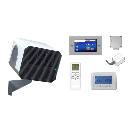
- Page 5 2. Introduction 2.4 Controllers Controlling heaters using CRXSL wireless controller CRXSL works on the same principle as HRXSL CRXSL 30m maximum distance Controlling heaters using CHMC Touchscreen Controller Maximum 8 heaters CHMC MCBMS provides external switch function and BMS fault reporting CHES environmental sensor 2 CHES or 1 CHES + 1 MCBMS in system 3.
- Page 6 4. Selecting heater controls 4.1 CRXSL or HRXSL Controller 4.3 Heater status indication The heater has to be configured for a se- Light colour Heater status lected control method at the time of instal- Heater is in stand-by mode/ not lation.
- Page 7 4. Selecting heater controls 4.5 CHMC Controller The heater has to be configured for a se- lected control method at the time of instal- lation. To control the heater using a CHMC controller the DIP switch 1 located under the electrical connections cover has to be set to ‘0’...
- Page 8 6. Installation Details 6.1 Mounting Figure 2: Swivel Bracket Assembly It is the sole responsibility of the installer to en- sure that the points of attachment to the building are sound. Consultation with the con- sultant/architect or owner of the building is recommended to ensure that a sound, me- chanically stable installation is achieved.
- Page 9 7. Technical Specifications 7.1 General Data FH6CPi FH9CPi FH12CPi Installation height 2 - 3.4 Heat medium Electric heating element Heat output Fan type EC centrifugal fan 133-190 Fan control Electronic fan speed control Heat switching Solid state electronic control Weight...
- Page 10 7. Technical Specifications 7.2 General Data FH6CSi Installation height 2 - 3.4 Heat medium Electric heating element Heat output Fan type EC centrifugal fan 133-190 Fan control Electronic fan speed control Switching type Solid state electronic control Weight Electrical Data Supply voltage 240V ~ 50Hz single phase only Total load...
- Page 11 8. Wiring Details 8.1 Installer Wiring - 3 phase heaters CAT5 cable 51000486 Iss 06...
- Page 12 8. Wiring Details 8.2 Installer Wiring - single phase heaters CAT5 cable 51000486 Iss 06...
- Page 13 Factory Wiring - 3 phase heaters 51000486 Iss 06...
- Page 14 Factory Wiring - single phase heaters 51000486 Iss 06...
- Page 15 9. Fault detection / indication 9.1 Fault detection 9.3 Status indication - secondary PCB Heaters are equipped with electronic fault A green LED on secondary PCBs shows that detection. In the event of a fault being de- there is power available. The red LED will tected, heater will show the nature of the fault flash one of the sequences as shown in the by flashing status LED located at the front of...
- Page 16 10. BMS Connection MODBUS Protocol 10.1 BMS Connection 16 Bit Input Registers: There are 2 ways for connecting heaters to BMS. 1 Status Using CHES or MCBMS and external switch as a 2 Inlet air temperature/back of the heater simple BMS on/off connection. Basic BMS fault 3 N/A reporting is also available with these devices.
- Page 17 Declaration Of Conformity In accordance with UK Government Guidance. E HEREBY CERTIFY THAT THE APPLIANCES DETAILED HEREON HAVE BEEN INSPECTED AND TESTED AND CONFORM TO THE REQUIREMENTS OF THE FOLLOWING UK STATUTORY INSTRUMENTS WHERE APPLICABLE Electrical Equipment (Safety) Regulations 2016 SI. 2016 1101 Electromagnetic Compatibility Regulations 2016 SI.
Need help?
Do you have a question about the FH6CPi and is the answer not in the manual?
Questions and answers