
Related Manuals for Flexiheat LEO COOL L3


Summary of Contents for Flexiheat LEO COOL L3
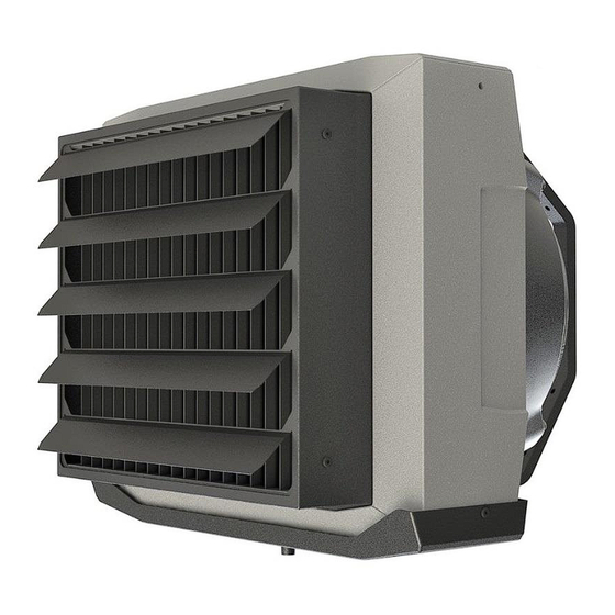
- Page 1 LEO COOL L3 LEO COOL XL4 FAN COOLER / HEATER TECHNICAL DOCUMENTATION OPERATION MANUAL...
-
Page 2: Table Of Contents
TABLE OF CONTENTS 1. Application ....................3 2. Technical Data ..................4 3. Installation ....................6 3.1. Installation – bracket .................6 3.2. Assembly instructions ...............6 4. Connection diagrams ................7 5. Start-Up and Operation ................10 6. Service and warranty terms ..............13 7. Conformity with WEEE directive 2012/19/UE ......... 14... -
Page 3: Application
1. APPLICATION LEO fan coolers/heaters make up a decentralised cooling/heating system. streaming through heat exchanger cooled/warmed up. Fan coolers/heaters are used for cooling/heating large volume buildings: general, industrial and public buildings etc. The casing of LEO fan coolers/heaters is made from extended polypropylene EPP. -
Page 4: Technical Data
2. TECHNICAL DATA LEO COOL L3 LEO COOL L3 Gear Max airflow [m3/h ] 2900 2050 1150 Power supply [V/Hz] 230/50 Max current consumption [A] Max power consumption [W] IP/ Insulation class 54 /F Max acoustic pressure level [dB(A)]* 64.1 54.5... - Page 5 2. TECHNICAL DATA LEO COOL XL4 LEO COOL XL4 Gear Max airflow [m3/h ] 4200 3350 2000 Power supply [V/Hz] 230/50 Max current consumption [A] Max power consumption [W] IP/ Insulation class 54 /F Max acoustic pressure level [dB(A)]* 67.5 61.1 52.3 Horizontal range** [m]...
-
Page 6: Installation
3. INSTALLTION Units can be mounted to vertical partitions using rotary console. The device should be leveled L3 COOL XL4 COOL 2.5 -7.0 2.5 -7.0 3.1. INSTALLATION – BRACKET 3.2. ASSEMBLY INSTRUCTIONS M8 screws are in set with bracket (option) Connect pipe for draining condensate... -
Page 7: Connection Diagrams
4. CONNECTION DIAGRAMS... - Page 8 4. CONNECTION DIAGRAMS Glands 6 x PG9 + 2 x PG 11 Wires size and type should be chosen by the designer EN: When connecting DRV modules to the T-box controller or BMS, you have to binary set addresses on each (each DRV must have individual address) DRV module by DIP-switch SW1.
- Page 9 DRV modules can be connected to the BMS (Building Management System). | BMS / GBS WARNING: The connection must be carried out with 3-wire (recommended UTP) to connectors DRV IN...
-
Page 10: Start-Up And Operation
5. START-UP AND OPERATION Guidelines for System Connection Periodic inspections In the case of devices intended for cooling, control valves cutting off the To keep proper technical parameters it is recommended periodic flow of the medium through the exchanger should be used. In the service (every 6 months) of fan heaters on behalf of the user. -
Page 11: Service And Warranty Terms
6. SERVICE AND WARRANTY TERMS Please contact your dealer in order to get familiar with the warranty terms and its limitation. In the case of any irregularities in the device operation, please contact the manufacturer’s service department. The manufacturer bears no responsibility for operating the device in a manner inconsistent with its purpose, by persons not authorised for this, and for damage resulting from this! | 13... -
Page 12: Conformity With Weee Directive 2012/19/Ue
7. CONFORMITY WITH WEEE DIRECTIVE 2012/19/UE Running a business without harming the environment and observing the rules of proper handling of waste electrical and electronic equipment is a priority The symbol of the crossed out wheeled bin placed on the equipment, packaging or documents attached means that the product must not be disposed of with other wastes. - Page 13 Declaration Of Conformity We hereby confirms the heating/cooling unit LEO COOL L3 LEO COOL XL4 was produced in accordance to the following Europeans Directives: 2014/30/UE – Electromagnetic Compatibility (EMC) 2006/42/WE – Machinery 2014/35/UE – Low Voltage Electrical Equipment (LVD) 2009/125/WE –...
- Page 14 Unit name: LEO COOL Capacity control: 3-speed Model Item Symbol Value Unit LEO COOL L3 12,4 Heating capacity rated,h LEO COOL XL4 24,9 ** heating capacity for parameters: inlet water temp. 45°C, water temperature drop 5°C, room air temp. 20°C.
- Page 16 | 19...
- Page 17 56073 MT-DTR-LEO-COOL-EN-PL-RU-V2.1 20 |...
Need help?
Do you have a question about the LEO COOL L3 and is the answer not in the manual?
Questions and answers