Advertisement
Quick Links
www.ti.com
EVM User's Guide: LM5125EVM-BST
LM5125EVM-BST Evaluation Module
Description
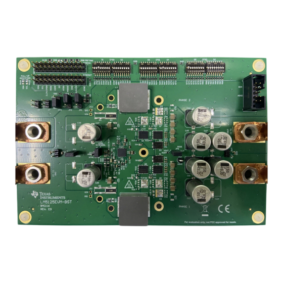
The LM5125EVM-BST evaluation module showcases
the features and performance of the LM5125-Q1
wide input voltage synchronous dual-phase boost
controller. This EVM is designed for ease of
configuration, enabling the user to evaluate different
conditions on the module. The standard configuration
is designed to provide a 24V/300W output. The output
voltage can be dynamically adjusted through the
ATRK/DTRK pin.
Get Started
1. Set the jumpers and DIP switches properly
2. Connect EVM to power supply and load
SNVU874 – DECEMBER 2024
Submit Document Feedback
Features
•
Two phase interleaved boost converter
•
Output voltage tracking from analog/PWM
•
Bypass mode
•
Optional Dual Random Spread Spectrum (DRSS)
•
Programmable undervoltage lockout (UVLO), Soft-
start, and dead time
•
Comprehensive fault protections
– Peak current limit
– Average current limit
– Over voltage protection
•
Stackable with two EVMs
Applications
•
Automotive Class H audio power amplifier
•
Automotive LED headlight applications
Copyright © 2024 Texas Instruments Incorporated
Description
LM5125EVM-BST Evaluation Module
1
Advertisement

Related Manuals for Texas Instruments LM5125EVM-BST


Summary of Contents for Texas Instruments LM5125EVM-BST
- Page 1 Description EVM User's Guide: LM5125EVM-BST LM5125EVM-BST Evaluation Module Description Features The LM5125EVM-BST evaluation module showcases • Two phase interleaved boost converter the features and performance of the LM5125-Q1 • Output voltage tracking from analog/PWM wide input voltage synchronous dual-phase boost •...
- Page 2 1 Evaluation Module Overview 1.1 Introduction The LM5125EVM-BST evaluation module provides a fully functional dual phase synchronous boost converter to evaluate LM5125-Q1. The EVM operates over an input voltage range of 8V to 18V and can handle input transients up to 42V. The EVM provides an output voltage of 24V with 300W rated power and 1kW peak power.
- Page 3 ILIM/IMON to the secondary EVM SCL to the secondary EVM SDA to the secondary EVM 2, 4, 6, 8, 10, 12, 14, 16, 18, 20, 22, 24 SNVU874 – DECEMBER 2024 LM5125EVM-BST Evaluation Module Submit Document Feedback Copyright © 2024 Texas Instruments Incorporated...
- Page 4 The CFG1 pin setting defines the V Over Voltage Protection level, Clock Dithering, the 120% input current limit protection (I ) operation, and the power good pin behavior. CL_latch LM5125EVM-BST Evaluation Module SNVU874 – DECEMBER 2024 Submit Document Feedback Copyright © 2024 Texas Instruments Incorporated...
- Page 5 – S1-postion 1 selects Level 1, …, S1-postion 8 selects Level 8 – S2-postion 1 selects Level 9, …, S2-postion 8 selects Level 16 • S3 and S4 are for CFG1 SNVU874 – DECEMBER 2024 LM5125EVM-BST Evaluation Module Submit Document Feedback Copyright © 2024 Texas Instruments Incorporated...
- Page 6 Set V to 45V • Populate R91=0Ω to set V to 24V (default) • Populate R91=0Ω to set V to 45V Refer to Figure 2-1. LM5125EVM-BST Evaluation Module SNVU874 – DECEMBER 2024 Submit Document Feedback Copyright © 2024 Texas Instruments Incorporated...
- Page 7 Remove R11 and R13, then solder wires in the plated through holes for current probes. Refer to Figure 2-2. Figure 2-2. Observe the inductor current SNVU874 – DECEMBER 2024 LM5125EVM-BST Evaluation Module Submit Document Feedback Copyright © 2024 Texas Instruments Incorporated...
- Page 8 Figure 3-2. Connecting the Primary EVM and Secondary EVM with Ribbon Cable 3.1.3 Test Procedure 1. Make sure the jumpers and DIP switches are set properly. 2. Prepare the setup following Figure 3-1. LM5125EVM-BST Evaluation Module SNVU874 – DECEMBER 2024 Submit Document Feedback Copyright © 2024 Texas Instruments Incorporated...
- Page 9 4. The load and input voltage may be changed as required. 3.1.4 Precautions Caution Hot surface. Caution Contact can cause burns. Do not touch! SNVU874 – DECEMBER 2024 LM5125EVM-BST Evaluation Module Submit Document Feedback Copyright © 2024 Texas Instruments Incorporated...
- Page 10 C2: SW2, 10V/div C3: I , 2A/div C4: I , 2A/div Figure 4-5. V = 14.4V, V = 24V, DEM, I = 15A load LM5125EVM-BST Evaluation Module SNVU874 – DECEMBER 2024 Submit Document Feedback Copyright © 2024 Texas Instruments Incorporated...
- Page 11 = 0A, Figure 4-9. V = 14.4V, V = 24V, FPWM, I = 0A, load load CFG2 = Level 13 CFG2 = Level 11 SNVU874 – DECEMBER 2024 LM5125EVM-BST Evaluation Module Submit Document Feedback Copyright © 2024 Texas Instruments Incorporated...
- Page 12 Figure 4-10. V = 14.4V, V = 24V, P = 300W, Figure 4-11. V = 14.4V, V = 45V, P = 300W, Natural Convection Natural Convection LM5125EVM-BST Evaluation Module SNVU874 – DECEMBER 2024 Submit Document Feedback Copyright © 2024 Texas Instruments Incorporated...
- Page 13 13.3k 13.3k 13.3k 16.2k 16.2k 16.2k 20.5k 20.5k 20.5k 24.9k 24.9k 24.9k 30.1k 30.1k 30.1k 36.5k 36.5k 36.5k AGND AGND AGND SNVU874 – DECEMBER 2024 LM5125EVM-BST Evaluation Module Submit Document Feedback Figure 5-1. Schematic Copyright © 2024 Texas Instruments Incorporated...
- Page 14 Hardware Design Files www.ti.com 5.2 PCB Layers Figure 5-2. Top Silk Screen Figure 5-3. Bottom Silk Screen LM5125EVM-BST Evaluation Module SNVU874 – DECEMBER 2024 Submit Document Feedback Copyright © 2024 Texas Instruments Incorporated...
- Page 15 Hardware Design Files Figure 5-4. Top Layer Figure 5-5. Signal Layer 1 SNVU874 – DECEMBER 2024 LM5125EVM-BST Evaluation Module Submit Document Feedback Copyright © 2024 Texas Instruments Incorporated...
- Page 16 Hardware Design Files www.ti.com Figure 5-6. Signal Layer 2 Figure 5-7. Signal Layer 3 LM5125EVM-BST Evaluation Module SNVU874 – DECEMBER 2024 Submit Document Feedback Copyright © 2024 Texas Instruments Incorporated...
- Page 17 Hardware Design Files Figure 5-8. Signal Layer 4 Figure 5-9. Bottom Layer SNVU874 – DECEMBER 2024 LM5125EVM-BST Evaluation Module Submit Document Feedback Copyright © 2024 Texas Instruments Incorporated...
- Page 18 RES, 0.0015, 5%, 2W, 2512 WIDE PML100HZPJV1L5 Rohm RES, 20.0 k, 1%, 0.1W, AEC-Q200 Grade 0, 0603 CRCW060320K0FKEA Vishay-Dale RES, 78.7 k, 0.1%, 0.1W, 0603 RT0603BRD0778K7L Yageo America LM5125EVM-BST Evaluation Module SNVU874 – DECEMBER 2024 Submit Document Feedback Copyright © 2024 Texas Instruments Incorporated...
- Page 19 Sullins Connector Solutions JP4, SH-JP5, SH-JP6 T1, T2, T3, T4 Terminal 70A Lug CXS70-14-C Panduit TP1, TP2, TP3, TP4 PC Test Point, SMT RCU-0C TE Connectivity SNVU874 – DECEMBER 2024 LM5125EVM-BST Evaluation Module Submit Document Feedback Copyright © 2024 Texas Instruments Incorporated...
- Page 20 Quantity Description Part Number Manufacturer Test Point, Compact, Black, TH 5006 Keystone Electronics Wide-VIN, 2.2MHz dual-phase boost controller with VOUT tracking LM5125QRHBRQ1 Texas Instruments LM5125EVM-BST Evaluation Module SNVU874 – DECEMBER 2024 Submit Document Feedback Copyright © 2024 Texas Instruments Incorporated...
- Page 21 Additional Information 6 Additional Information Trademarks All trademarks are the property of their respective owners. SNVU874 – DECEMBER 2024 LM5125EVM-BST Evaluation Module Submit Document Feedback Copyright © 2024 Texas Instruments Incorporated...
- Page 22 STANDARD TERMS FOR EVALUATION MODULES Delivery: TI delivers TI evaluation boards, kits, or modules, including any accompanying demonstration software, components, and/or documentation which may be provided together or separately (collectively, an “EVM” or “EVMs”) to the User (“User”) in accordance with the terms set forth herein.
- Page 23 www.ti.com Regulatory Notices: 3.1 United States 3.1.1 Notice applicable to EVMs not FCC-Approved: FCC NOTICE: This kit is designed to allow product developers to evaluate electronic components, circuitry, or software associated with the kit to determine whether to incorporate such items in a finished product and software developers to write software applications for use with the end product.
- Page 24 www.ti.com Concernant les EVMs avec antennes détachables Conformément à la réglementation d'Industrie Canada, le présent émetteur radio peut fonctionner avec une antenne d'un type et d'un gain maximal (ou inférieur) approuvé pour l'émetteur par Industrie Canada. Dans le but de réduire les risques de brouillage radioélectrique à...
- Page 25 www.ti.com EVM Use Restrictions and Warnings: 4.1 EVMS ARE NOT FOR USE IN FUNCTIONAL SAFETY AND/OR SAFETY CRITICAL EVALUATIONS, INCLUDING BUT NOT LIMITED TO EVALUATIONS OF LIFE SUPPORT APPLICATIONS. 4.2 User must read and apply the user guide and other available documentation provided by TI regarding the EVM prior to handling or using the EVM, including without limitation any warning or restriction notices.
- Page 26 Notwithstanding the foregoing, any judgment may be enforced in any United States or foreign court, and TI may seek injunctive relief in any United States or foreign court. Mailing Address: Texas Instruments, Post Office Box 655303, Dallas, Texas 75265 Copyright © 2023, Texas Instruments Incorporated...
- Page 27 TI products. TI’s provision of these resources does not expand or otherwise alter TI’s applicable warranties or warranty disclaimers for TI products. TI objects to and rejects any additional or different terms you may have proposed. IMPORTANT NOTICE Mailing Address: Texas Instruments, Post Office Box 655303, Dallas, Texas 75265 Copyright © 2024, Texas Instruments Incorporated...
Need help?
Do you have a question about the LM5125EVM-BST and is the answer not in the manual?
Questions and answers