Table of Contents
Advertisement
Quick Links
www.ti.com
EVM User's Guide: LM5190QEVM-400
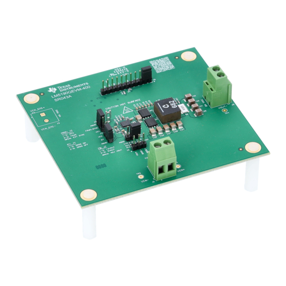
LM5190-Q1 CCCV Buck Controller Evaluation Module
Description
The
LM5149Q1EVM-400
a synchronous buck DC/DC regulator with constant-
current constant-voltage (CCCV) regulation. The EVM
operates over a wide input voltage range of 15V to
72V (at J1 VIN terminal), providing a regulated current
of 8A in CC mode and a regulated voltage of 12V
in CV mode. The regulation target of the average
inductor current is programmed by ISET and the
output voltage is adjusted by modifying the feedback
resistors.
Features
•
Wide input voltage operating range
– 15V to 72V: VIN terminal
•
Fixed 12V, 5V, or adjustable output voltage
•
Adjustable average inductor current using ISET
•
Inductor current monitor using IMON
•
Integrated standard MOSFET gate drivers
•
18µA standby current at V
SLVUCY4 – JUNE 2024
Submit Document Feedback
evaluation module (EVM) is
= 48V with BIAS
SUPPLY
LM5190Q1EVM
Copyright © 2024 Texas Instruments Incorporated
•
Full-load efficiency of 95% at V
•
400kHz switching frequency with optional external
clock synchronization
•
Dual-random spread spectrum
•
Integrated slope compensation
•
Forced PWM (FPWM) or pulsed-frequency
modulation (PFM) operation
•
Over-current protection (OCP) with hiccup mode
for abnormal overload conditions
•
Power Good indicator with pullup resistor to VCC
•
Internal 2.75ms soft start in CV mode
•
CC mode soft start using C
•
Thermally efficient layout with 6-layer 2-oz PCB
Applications
•
Super capacitor energy backup
•
E-bikes
•
Power tools
•
Server battery-backup unit (BBU)
•
Energy storage system
LM5190-Q1 CCCV Buck Controller Evaluation Module
Description
= 48V
SUPPLY
capacitor
ISET
and
solar energy
1
Advertisement
Table of Contents

Related Manuals for Texas Instruments LM5190-Q1


Summary of Contents for Texas Instruments LM5190-Q1
- Page 1 Description EVM User's Guide: LM5190QEVM-400 LM5190-Q1 CCCV Buck Controller Evaluation Module • Full-load efficiency of 95% at V = 48V Description SUPPLY • 400kHz switching frequency with optional external LM5149Q1EVM-400 evaluation module (EVM) is clock synchronization a synchronous buck DC/DC regulator with constant- •...
-
Page 2: Kit Contents
0.8V to 42V 100kHz to 2.2MHz Standard AEC-Q100 Grdae1 LM5190-Q1 5V to 80V 0.8V to 80V 100kHz to 2.2MHz Standard AEC-Q100 Grade1 LM5190-Q1 CCCV Buck Controller Evaluation Module SLVUCY4 – JUNE 2024 Submit Document Feedback Copyright © 2024 Texas Instruments Incorporated... -
Page 3: Evm Connections
VIN_EMI– Negative input voltage power connection for EMI test. VOUT+ Positive output voltage power connection. VOUT– Negative output voltage power connection. SLVUCY4 – JUNE 2024 LM5190-Q1 CCCV Buck Controller Evaluation Module Submit Document Feedback Copyright © 2024 Texas Instruments Incorporated... - Page 4 50Ω injection point for CV loop response measurement. Connected to feedback resistor. BODE+ 50Ω injection point for CV loop response measurement. Connected to output capacitor. LM5190-Q1 CCCV Buck Controller Evaluation Module SLVUCY4 – JUNE 2024 Submit Document Feedback Copyright © 2024 Texas Instruments Incorporated...
- Page 5 9. Turn off the input power source. SLVUCY4 – JUNE 2024 LM5190-Q1 CCCV Buck Controller Evaluation Module Submit Document Feedback Copyright © 2024 Texas Instruments Incorporated...
- Page 6 SUPPLY =60V SUPPLY 0.001 0.002 0.005 0.01 0.02 0.05 0.2 0.3 0.5 Output Current [A] Figure 3-2. PFM mode, Log Scale LM5190-Q1 CCCV Buck Controller Evaluation Module SLVUCY4 – JUNE 2024 Submit Document Feedback Copyright © 2024 Texas Instruments Incorporated...
- Page 7 3.1.2.2 Switching VOUT 100mV/DIV , AC COUPLED ILOUT 5A/DIV Figure 3-5. Output Ripple, V = 48V, I = 8A SUPPLY LOAD SLVUCY4 – JUNE 2024 LM5190-Q1 CCCV Buck Controller Evaluation Module Submit Document Feedback Copyright © 2024 Texas Instruments Incorporated...
- Page 8 = 48V, FPWM, 0A to 4A SUPPLY VOUT 1V/DIV ILOUT 5A/DIV Figure 3-8. Load Transient Response, V = 48V, PFM, 0A to 4A SUPPLY LM5190-Q1 CCCV Buck Controller Evaluation Module SLVUCY4 – JUNE 2024 Submit Document Feedback Copyright © 2024 Texas Instruments Incorporated...
-
Page 9: Thermal Performance
LOAD 3.1.3 Thermal Performance Figure 3-10. Thermal Performance, V = 48V, I = 8A, T = 25°C, No Airflow SUPPLY LOAD SLVUCY4 – JUNE 2024 LM5190-Q1 CCCV Buck Controller Evaluation Module Submit Document Feedback Copyright © 2024 Texas Instruments Incorporated... - Page 10 SUPPLY LOAD LOAD 3.1.5 EMI Performance Figure 3-12. 150kHz to 30MHz, V = 48V, R = 1.5Ω, DRSS OFF SUPPLY LOAD LM5190-Q1 CCCV Buck Controller Evaluation Module SLVUCY4 – JUNE 2024 Submit Document Feedback Copyright © 2024 Texas Instruments Incorporated...
- Page 11 Implementation Results Figure 3-13. 150kHz to 30MHz, V = 48V, R = 1.5Ω, DRSS ON SUPPLY LOAD SLVUCY4 – JUNE 2024 LM5190-Q1 CCCV Buck Controller Evaluation Module Submit Document Feedback Copyright © 2024 Texas Instruments Incorporated...
- Page 12 Jumper ¢ AGND ILIM/IMON ILIM/IMON AGND ISET ISET VOUT COMP COMP AGND BIAS BIAS VOUT Figure 4-1. EVM Schematic LM5190-Q1 CCCV Buck Controller Evaluation Module SLVUCY4 – JUNE 2024 Submit Document Feedback Copyright © 2024 Texas Instruments Incorporated...
-
Page 13: Pcb Layout
LM5190 EVM uses a 6-layer PCB with 2-oz copper thickness. Figure 4-2. Top Components (Top View) Figure 4-3. Bottom Components (Bottom View) SLVUCY4 – JUNE 2024 LM5190-Q1 CCCV Buck Controller Evaluation Module Submit Document Feedback Copyright © 2024 Texas Instruments Incorporated... - Page 14 Hardware Design Files www.ti.com Figure 4-4. Top Layer Copper (Top View) Figure 4-5. Layer 2 Copper (Top View) LM5190-Q1 CCCV Buck Controller Evaluation Module SLVUCY4 – JUNE 2024 Submit Document Feedback Copyright © 2024 Texas Instruments Incorporated...
- Page 15 Hardware Design Files Figure 4-6. Layer 3 Copper (Top View) Figure 4-7. Layer 4 Copper (Top View) SLVUCY4 – JUNE 2024 LM5190-Q1 CCCV Buck Controller Evaluation Module Submit Document Feedback Copyright © 2024 Texas Instruments Incorporated...
- Page 16 Hardware Design Files www.ti.com Figure 4-8. Layer 5 Copper (Top View) Figure 4-9. Bottom Copper (Top View) LM5190-Q1 CCCV Buck Controller Evaluation Module SLVUCY4 – JUNE 2024 Submit Document Feedback Copyright © 2024 Texas Instruments Incorporated...
-
Page 17: Bill Of Materials
™ PowerPAD is a trademark of Texas Instruments. ® WEBENCH is a registered trademark of Texas Instruments. All trademarks are the property of their respective owners. SLVUCY4 – JUNE 2024 LM5190-Q1 CCCV Buck Controller Evaluation Module Submit Document Feedback Copyright © 2024 Texas Instruments Incorporated... -
Page 18: Documentation Support
PowerPAD ™ Thermally Enhanced Package Application Report • PowerPAD ™ Made Easy Application Brief • Using New Thermal Metrics Application Report LM5190-Q1 CCCV Buck Controller Evaluation Module SLVUCY4 – JUNE 2024 Submit Document Feedback Copyright © 2024 Texas Instruments Incorporated... - Page 19 STANDARD TERMS FOR EVALUATION MODULES Delivery: TI delivers TI evaluation boards, kits, or modules, including any accompanying demonstration software, components, and/or documentation which may be provided together or separately (collectively, an “EVM” or “EVMs”) to the User (“User”) in accordance with the terms set forth herein.
- Page 20 www.ti.com Regulatory Notices: 3.1 United States 3.1.1 Notice applicable to EVMs not FCC-Approved: FCC NOTICE: This kit is designed to allow product developers to evaluate electronic components, circuitry, or software associated with the kit to determine whether to incorporate such items in a finished product and software developers to write software applications for use with the end product.
- Page 21 www.ti.com Concernant les EVMs avec antennes détachables Conformément à la réglementation d'Industrie Canada, le présent émetteur radio peut fonctionner avec une antenne d'un type et d'un gain maximal (ou inférieur) approuvé pour l'émetteur par Industrie Canada. Dans le but de réduire les risques de brouillage radioélectrique à...
- Page 22 www.ti.com EVM Use Restrictions and Warnings: 4.1 EVMS ARE NOT FOR USE IN FUNCTIONAL SAFETY AND/OR SAFETY CRITICAL EVALUATIONS, INCLUDING BUT NOT LIMITED TO EVALUATIONS OF LIFE SUPPORT APPLICATIONS. 4.2 User must read and apply the user guide and other available documentation provided by TI regarding the EVM prior to handling or using the EVM, including without limitation any warning or restriction notices.
- Page 23 Notwithstanding the foregoing, any judgment may be enforced in any United States or foreign court, and TI may seek injunctive relief in any United States or foreign court. Mailing Address: Texas Instruments, Post Office Box 655303, Dallas, Texas 75265 Copyright © 2023, Texas Instruments Incorporated...
- Page 24 TI products. TI’s provision of these resources does not expand or otherwise alter TI’s applicable warranties or warranty disclaimers for TI products. TI objects to and rejects any additional or different terms you may have proposed. IMPORTANT NOTICE Mailing Address: Texas Instruments, Post Office Box 655303, Dallas, Texas 75265 Copyright © 2024, Texas Instruments Incorporated...
Need help?
Do you have a question about the LM5190-Q1 and is the answer not in the manual?
Questions and answers