Advertisement
www.ti.com
EVM User's Guide: LM51772EVM
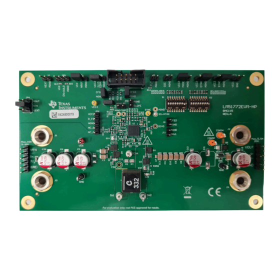
LM51772 Buck-Boost Controller Evaluation Module
Description
The
LM51772EVM-HP
demonstrates a flexible high
power Buck-Boost design using the LM51772. The
LM51772 is a wide-V
four switch Buck-Boost
IN
controller. The device provides a regulated output
voltage if the input voltage is higher, equal or lower as
the adjusted output voltage. In power safe mode, the
device supports a superb efficiency over the full range
of the output. The evaluation module is configured to
operate from input voltage range of 9.0V to 48V and
produce a regulated 20V output with up to 5A load
current.
Get Started
1. Connect EVM to power supply and load
2. For using the Configuration GUI and I2C
operation, the
USB2ANY
3. Install the LM51772 Configuration GUI
Features
•
Wide input voltage range
•
Ultra high (> 95%) peak power conversion
efficiency
SNVU852A – SEPTEMBER 2023 – REVISED MARCH 2024
Submit Document Feedback
adapter can be used
Copyright © 2024 Texas Instruments Incorporated
•
Adjustable output voltage using feedback resistor
divider or I2C interface
•
Optional synchronization (SYNC)
•
Easy configuration of current monitor or limiter
•
Support for cable drop compensation
•
Output disconnect support
•
Programmable input undervoltage lockout (UVLO)
threshold and hysteresis
•
Output constant voltage (CV) and constant current
(CC) options
•
I2C interface with USB2ANY and GUI
•
Setting of configuration resistor R
switches
Applications
®
•
USB Type-C
power delivery
–
Docking station
–
PC monitor
–
Desktop PC
•
Wireless charging
•
Industrial PC
and
rugged PC
•
Docking station
•
Battery backup unit (BBU)
•
Merchant DC/DC
LM51772 Buck-Boost Controller Evaluation Module
Description
through DIP
CFG2
1
Advertisement
Table of Contents

Related Manuals for Texas Instruments LM51772EVM


Summary of Contents for Texas Instruments LM51772EVM
- Page 1 Docking station • Ultra high (> 95%) peak power conversion • Battery backup unit (BBU) efficiency • Merchant DC/DC SNVU852A – SEPTEMBER 2023 – REVISED MARCH 2024 LM51772 Buck-Boost Controller Evaluation Module Submit Document Feedback Copyright © 2024 Texas Instruments Incorporated...
-
Page 2: Kit Contents
Operation mode selection for high light load efficiency – Power save burst mode – μSleep power save mode • Integrated high voltage supply LDO LM51772 Buck-Boost Controller Evaluation Module SNVU852A – SEPTEMBER 2023 – REVISED MARCH 2024 Submit Document Feedback Copyright © 2024 Texas Instruments Incorporated... -
Page 3: Connector Descriptions
RT external input connection DRV1 measure and external input connector I2C / USB2ANY connector VCC1 output connector CDC output connector SNVU852A – SEPTEMBER 2023 – REVISED MARCH 2024 LM51772 Buck-Boost Controller Evaluation Module Submit Document Feedback Copyright © 2024 Texas Instruments Incorporated... -
Page 4: Jumper Descriptions
Pin 1 to Pin 2 Set jumper to enable config setting for no I2C operation JP12 Open Remove jumper for I2C operation LM51772 Buck-Boost Controller Evaluation Module SNVU852A – SEPTEMBER 2023 – REVISED MARCH 2024 Submit Document Feedback Copyright © 2024 Texas Instruments Incorporated... - Page 5 DISABLED ENABLED ENABLED ENABLED DISABLED DISABLED ENABLED ENABLED DISABLED ENABLED ENABLED Note Only one switch must be closed! SNVU852A – SEPTEMBER 2023 – REVISED MARCH 2024 LM51772 Buck-Boost Controller Evaluation Module Submit Document Feedback Copyright © 2024 Texas Instruments Incorporated...
- Page 6 – Current limit: enabled Note The LM51772EVM-HP has been configured with disabled I2C operation with JP8 not set. The slope compensation default setting is 0.875. If this needs to be changed, then the slope compensation default setting can be set through I2C command or replacing R20 with the corresponding resistor.
- Page 7 Implementation Results 3 Implementation Results 3.1 Test Setup and Procedure 3.1.1 Test Setup Figure 3-1 shows a typical test setup to evaluate the LM51772EVM-HP. Power Supply Ammeter 1 Ammeter 2 Electronic Load Voltmeter 1 Voltmeter 2 Figure 3-1. Typical EVM Connection Diagram 3.1.2 Test Procedure...
- Page 8 Figure 3-5. Thermal Image: V = 48V, I = 5.0A, No Forced Air Cooling No Forced Air Cooling LM51772 Buck-Boost Controller Evaluation Module SNVU852A – SEPTEMBER 2023 – REVISED MARCH 2024 Submit Document Feedback Copyright © 2024 Texas Instruments Incorporated...
- Page 9 96.5 95.5 94.5 93.5 VIN [V] Figure 3-7. Efficiency vs. Input Voltage, V = 20V, I = 5A SNVU852A – SEPTEMBER 2023 – REVISED MARCH 2024 LM51772 Buck-Boost Controller Evaluation Module Submit Document Feedback Copyright © 2024 Texas Instruments Incorporated...
- Page 10 Figure 3-12. SW1, SW2, I = 16V, I = 0A) Figure 3-13. SW1, SW2, I = 16V, I = 5.0A) LM51772 Buck-Boost Controller Evaluation Module SNVU852A – SEPTEMBER 2023 – REVISED MARCH 2024 Submit Document Feedback Copyright © 2024 Texas Instruments Incorporated...
- Page 11 Figure 3-16. SW1, SW2, I = 36V, I = 0A) Figure 3-17. SW1, SW2, I = 36V, I = 5.0A) SNVU852A – SEPTEMBER 2023 – REVISED MARCH 2024 LM51772 Buck-Boost Controller Evaluation Module Submit Document Feedback Copyright © 2024 Texas Instruments Incorporated...
- Page 12 = 24V, I = 2A – 5A) Figure 3-22. Load Step (V = 36V, I = 2A – 5A) LM51772 Buck-Boost Controller Evaluation Module SNVU852A – SEPTEMBER 2023 – REVISED MARCH 2024 Submit Document Feedback Copyright © 2024 Texas Instruments Incorporated...
-
Page 13: Frequency (Hz)
500 1000 10000 100000 1000000 Frequency (Hz) Figure 3-23. Control Loop Response, VIN = 9.0V, IOUT = 5.0A SNVU852A – SEPTEMBER 2023 – REVISED MARCH 2024 LM51772 Buck-Boost Controller Evaluation Module Submit Document Feedback Copyright © 2024 Texas Instruments Incorporated... - Page 14 VBUS is not required to be connected USB2ANY interface has an internal 3.3V VBUS supply Figure 4-1. 4-Switch Buck-Boost Controller Schematic LM51772 Buck-Boost Controller Evaluation Module SNVU852A – SEPTEMBER 2023 – REVISED MARCH 2024 Submit Document Feedback Copyright © 2024 Texas Instruments Incorporated...
- Page 15 Hardware Design Files 4.2 PCB Layout Figure 4-2 through Figure 4-7 show the design of the LM51772EVM-HP PCB. Figure 4-2. Top Silkscreen Figure 4-3. Bottom Silkscreen SNVU852A – SEPTEMBER 2023 – REVISED MARCH 2024 LM51772 Buck-Boost Controller Evaluation Module Submit Document Feedback...
- Page 16 Hardware Design Files www.ti.com Figure 4-4. Top Layer Figure 4-5. Mid-Layer 1 LM51772 Buck-Boost Controller Evaluation Module SNVU852A – SEPTEMBER 2023 – REVISED MARCH 2024 Submit Document Feedback Copyright © 2024 Texas Instruments Incorporated...
- Page 17 Hardware Design Files Figure 4-6. Mid-Layer 2 Figure 4-7. Bottom Layer SNVU852A – SEPTEMBER 2023 – REVISED MARCH 2024 LM51772 Buck-Boost Controller Evaluation Module Submit Document Feedback Copyright © 2024 Texas Instruments Incorporated...
- Page 18 J7, J8, J9, J10, J11, J13, J14, JP8, JP10, JP11, Header, 2.54mm, 2x1, Gold, TH 61300211121 Wurth Elektronik JP12 LM51772 Buck-Boost Controller Evaluation Module SNVU852A – SEPTEMBER 2023 – REVISED MARCH 2024 Submit Document Feedback Copyright © 2024 Texas Instruments Incorporated...
- Page 19 RES, 1.15 k, 1%, 0.1 W, AEC-Q200 Grade 0, 0603 CRCW06031K15FKEA Vishay-Dale 1.87k RES, 1.87 k, 1%, 0.1 W, 0603 RC0603FR-071K87L Yageo SNVU852A – SEPTEMBER 2023 – REVISED MARCH 2024 LM51772 Buck-Boost Controller Evaluation Module Submit Document Feedback Copyright © 2024 Texas Instruments Incorporated...
- Page 20 Test Point, Multipurpose, Grey, TH 5128 Keystone Electronics TP10, TP11 Test Point, Miniature, Yellow, TH 5004 Keystone Electronics LM51772 Buck-Boost Controller Evaluation Module SNVU852A – SEPTEMBER 2023 – REVISED MARCH 2024 Submit Document Feedback Copyright © 2024 Texas Instruments Incorporated...
- Page 21 RES, 180 k, 5%, 0.1 W, AEC-Q200 Grade 0, 0603 CRCW0603180KJNEA Vishay-Dale R58, R59 RES, 3.0, 5%, 0.1 W, AEC-Q200 Grade 0, 0603 CRCW06033R00JNEA Vishay-Dale SNVU852A – SEPTEMBER 2023 – REVISED MARCH 2024 LM51772 Buck-Boost Controller Evaluation Module Submit Document Feedback Copyright © 2024 Texas Instruments Incorporated...
- Page 22 Test Point, Miniature, Yellow, TH 5004 Keystone Electronics TP14, TP16 Test Point, Miniature, Black, TH 5001 Keystone Electronics LM51772 Buck-Boost Controller Evaluation Module SNVU852A – SEPTEMBER 2023 – REVISED MARCH 2024 Submit Document Feedback Copyright © 2024 Texas Instruments Incorporated...
-
Page 23: Additional Information
• Updated Test Procedure section........................• Updated Efficiency figures..........................9 • Changed schematic............................• Updated Bill of Materials table..........................18 SNVU852A – SEPTEMBER 2023 – REVISED MARCH 2024 LM51772 Buck-Boost Controller Evaluation Module Submit Document Feedback Copyright © 2024 Texas Instruments Incorporated... - Page 24 STANDARD TERMS FOR EVALUATION MODULES Delivery: TI delivers TI evaluation boards, kits, or modules, including any accompanying demonstration software, components, and/or documentation which may be provided together or separately (collectively, an “EVM” or “EVMs”) to the User (“User”) in accordance with the terms set forth herein.
- Page 25 www.ti.com Regulatory Notices: 3.1 United States 3.1.1 Notice applicable to EVMs not FCC-Approved: FCC NOTICE: This kit is designed to allow product developers to evaluate electronic components, circuitry, or software associated with the kit to determine whether to incorporate such items in a finished product and software developers to write software applications for use with the end product.
- Page 26 www.ti.com Concernant les EVMs avec antennes détachables Conformément à la réglementation d'Industrie Canada, le présent émetteur radio peut fonctionner avec une antenne d'un type et d'un gain maximal (ou inférieur) approuvé pour l'émetteur par Industrie Canada. Dans le but de réduire les risques de brouillage radioélectrique à...
- Page 27 www.ti.com EVM Use Restrictions and Warnings: 4.1 EVMS ARE NOT FOR USE IN FUNCTIONAL SAFETY AND/OR SAFETY CRITICAL EVALUATIONS, INCLUDING BUT NOT LIMITED TO EVALUATIONS OF LIFE SUPPORT APPLICATIONS. 4.2 User must read and apply the user guide and other available documentation provided by TI regarding the EVM prior to handling or using the EVM, including without limitation any warning or restriction notices.
- Page 28 Notwithstanding the foregoing, any judgment may be enforced in any United States or foreign court, and TI may seek injunctive relief in any United States or foreign court. Mailing Address: Texas Instruments, Post Office Box 655303, Dallas, Texas 75265 Copyright © 2023, Texas Instruments Incorporated...
- Page 29 TI products. TI’s provision of these resources does not expand or otherwise alter TI’s applicable warranties or warranty disclaimers for TI products. TI objects to and rejects any additional or different terms you may have proposed. IMPORTANT NOTICE Mailing Address: Texas Instruments, Post Office Box 655303, Dallas, Texas 75265 Copyright © 2024, Texas Instruments Incorporated...
Need help?
Do you have a question about the LM51772EVM and is the answer not in the manual?
Questions and answers