Advertisement
Quick Links
Advertisement

Related Manuals for Teledyne Lecroy PP018-1


Summary of Contents for Teledyne Lecroy PP018-1
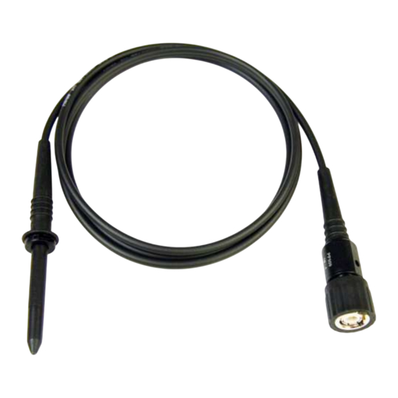
- Page 1 PP009-1 PP009-2 Operator’s Manual PP009 Passive Probe...
- Page 3 Spare parts, replacement parts and repairs are warranted for 90 days. In exercising its warranty, Teledyne LeCroy, at its option, will either repair or replace any assembly returned within its warranty period to the Customer Service Department or an authorized service center.
- Page 4 PP009 Passive Probe Safety Instructions This section contains instructions that must be observed to keep this oscilloscope accessory operating in a correct and safe condition. You are required to follow generally accepted safety procedures in addition to the precautions specified in this section. The overall safety of any system incorporating this accessory is the responsibility of the assembler of the system.
- Page 5 Operator’s Manual Do not overload. To avoid electric shock or fire, do not apply any potential to the probe leads that exceeds the maximum rating of the probe. Comply with voltage derating curve. When measuring higher frequency signals, comply with the Voltage vs. Frequency Derating Curve. Observe all terminal ratings.
- Page 6 DC through several hundred MHz. The PP009 has a large selection of connection accessories, supplied standard with the probe and available from Teledyne LeCroy as optional accessories. The PP009 is designed for use with 600 MHz and lower Teledyne LeCroy WaveSurfer Xs series oscilloscopes. 922222-00 Rev A...
- Page 7 Operator’s Manual Specifications Electrical Characteristics 10 1% Attenuation 10 M 1% Input Resistance Input Capacitance 9.5 pF Input Impedance (see plot on next page) Compensation Range 10 - 20 pF Bandwidth 500 MHz (-3 dB) Electrical Ratings* Maximum Input Voltage Measurement category I: 400 V rms, 1250 V transient overvoltage (see voltage derating curve on page 5)
- Page 8 PP009 Passive Probe Max. V versus Frequency, Measurement Category I Typical Input Impedance 922222-00 Rev A...
- Page 9 Operator’s Manual Connectivity Accessories Teledyne LeCroy provides 24 individual accessories for the PP009 probe, which enable reliable connections to any physical requirement. In addition to those provided with the standard probe, several optional varieties are available either individually, or grouped in sets related to specific application needs.
- Page 10 PP009 Passive Probe Optional Accessories IPS AND PRINGS PK1-5MM-109 PK1-5MM-124 PK1-5MM-108 PK1-5MM-118 Spring Tip, 0.8 mm Spring Tip, 0.38 mm IC Cap, 2.54 mm pitch Ground Spring NPUT DAPTERS AND LIPS PK1-5MM-111 PK1-5MM-112 PK1-5MM-116 PK1-5MM-117 Single Lead Adapter Dual Lead Adapter Adapter, 2 mm plug Adapter, 4 mm plug...
- Page 11 ROBE ONNECTIVITY The following kits containing an assortment of probe connection accessories can be ordered directly from Teledyne LeCroy. Refer to the illustrations on pages 4-6 for identification. PKIT1-5MM-102 Basic Adapter Kit replaces the common standard accessories, with 1 each of PK1-5MM-110, PK1-5MM-104, PK1-5MM-103, PK1-5MM-108, PK1-5MM-117, PK1-5MM-101, PK1-5MM-102, PK1-5MM-118, PK1-5MM-123;...
- Page 12 Use of PCB Adapter The PCB adapter (Teledyne LeCroy P/N PK1-5MM-107) is intended to be designed into and permanently installed in circuit boards to provide a reliable, high frequency test point which eliminates the need to hand hold the probe.
- Page 13 Operator’s Manual Probe Compensation Proper compensation of the probe is required to assure good amplitude accuracy in the dynamic portions of the waveform being measured. LF compensation matches the probe to differences in oscilloscope input capacitance. The LF compensation should always be checked and adjusted as needed when first connecting a passive probe to the oscilloscope input.
- Page 14 The PP009 probe is supplied with a rigid tip. The spring tips PK1-5MM-109 (0.8 mm) or PK1-5MM-124 (0.38 mm) combine sharp points with on-axis compliance and can be ordered directly from Teledyne LeCroy as optional accessories. All three tip styles provide reliable connections under a wide range of physical interconnect situations.
- Page 15 The probe is subject to disposal and recycling regulations that vary by country and region. Many countries prohibit the disposal of waste electronic equipment in standard waste receptacles. For more information about proper disposal and recycling of your Teledyne LeCroy product, please visit teledynelecroy.com/recycle. ESTRICTION OF AZARDOUS UBSTANCES...
- Page 16 Ph: 800-909-7112 / 408-653-1260 customersupport@teledynelecroy.com psgsupport@teledynelecroy.com European Headquarters Singapore, Oscillosocpes Teledyne LeCroy SA Teledyne LeCroy Singapore Pte Ltd. 4, Rue Moïse Marcinhes Blk 750C Chai Chee Road #02-08 Case postale 341 Technopark @ Chai Chee 1217 Meyrin 1 Singapore 469003...
- Page 17 Operator’s Manual 922222-00 Rev A...
- Page 18 PP009 Passive Probe 922222-00 Rev A...
Need help?
Do you have a question about the PP018-1 and is the answer not in the manual?
Questions and answers