Advertisement
Quick Links
HC8S Controller
trustworthy electrical control partner in the machine tool industry.
Basic Installation Instructions
Dear users, please go through the instructions in detail before the installation. Also, please hand the manual to
the actual operator of the machine and preserve it properly.
CNC controllers are precision electronic devices. For the safety of both operators and the machine, please
ensure all installations, tests, and adjustments are operated by professional personnel. For the description with
"DANGER", "WARNING" and "CAUTION" in the manual, please read them in detail. If there are any concerns,
please contact our branches in your region. Our professionals are glad to be at your service. The following are the
guidelines you should comply with before finishing reading the complete manual:
⚫
The installing environment should be indoor and without water vapor, corrosive or flammable gas.
⚫
Implement the wirings according to the wiring diagram.
⚫
The grounding must be strictly implemented and follow the current National Electrical Code.
(References: NFPA 70: National Electrical Code,2005 Ed.)
⚫
Do not modify the wirings while the device is powered up.
1.
Safety Precautions
Please pay extra attention to the instructions below while operating the product.
◼
Please install the controller according to the manual or it might cause damage to
the equipment.
◼
Do not operate the product in places exposed to water vapor, corrosive, or
flammable gases. It might cause damage to the device, electric shocks, fire, or
explosion.
◼
Do not install the product at a temperature exceeding the specified range. It
might cause device damage or malfunctioning.
◼
The controller series is designed to control the motor of the machine tool and
manage the IO control. Do not touch the internal circuits or components while
the controller is powered up. It might cause electric shock or device damage.
◼
The internal circuit board of the driver contains CMOS ICs, which are
vulnerable to static electricity. Do not touch the circuit board with your hands
before taking any precautions.
◼
The product has been tested and found to comply with the limits for a KC Class
A Commercial equipment) digital device. It was designed for use in
commercial and industrial environments instead of households.
◼ Do not apply the product to machines that might lead to casualties, device
damage, or system shut down.
◼
The controller is a precision instrument. Please prevent non-maintenance staff
or non-professional electronic control personnel from disassembling the
device.
◼
Please cut off all the external loads when powering up the controller for the first
time. The built-in testing PLC program may start the motor immediately after
power-up, which might be dangerous for the staffs around.
◼
Please apply the correct ground loop to prevent errors from the controller.
◼ Please separate the communication cable of the driver from all the other motor and
power cables with individual wiring ducks to prevent the controller from
malfunction caused by large noise interference.
◼
The CNC controller adopts a microcomputer design. Please install the
controller in a safe area and keep the area clean. Please keep iron shavings,
wires, water, corrosive gas, and liquid from the driver to avoid malfunction.
B01-HC8S-01-TC
◼
Storage temperature range: -20℃~60℃
Storage relative humidity range: 0% to 90% and without condensation.
High speed, High accuracy. The most
◼
Operating temperature range: -10℃~55℃
◼
Please install the product in a safe area and keep the area clean. Keep iron
shavings, wires, water, corrosive gas, and liquid from the product to avoid
malfunction.
V1.3
◼
The grounding of the controller and machine tool system is necessary for
leakage protection and prevention of lightning strikes. Please ensure the driver
and the machine tool system are grounded properly before installing.
◼
The rated voltage of the controller power system should not exceed DC18~32V.
If the operating environment provides an unstable voltage source, please apply
a voltage stabilizer so that the controller can function properly.
◼
Please turn off the power before plugging/unplugging the cables or modifying
the wirings to prevent electric shocks or damage to the driver.
◼
Please make sure all the terminals are in the correct positions while wiring to
prevent the driver from damage caused by wiring mistakes.
◼
Do not touch the terminals within 10 minutes after cutting off the power in case
the residual voltage might cause electric shocks.
◼
Do not touch the panel with sharp objects or it might cause malfunction due to
depression.
2.
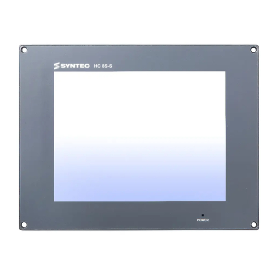
Interface Specifications
(Front View)
A
A
8-inch monitor
B
Display Window
B
Indicator Light
Indicator
(Rear View)
C
A
B
A
DC 24V INPUT
Power Input DC 24V‧1A
5 axes; each axis includes different signaling of
B
P1~P5
PULSE, DIR and ALM
4 points of Direct Output
C
OUTPUT PORT
(transistor for power supply 24V / 1A)
16 points of Direct Input (optical coupler; able to adjust
D
INPUT PORT
the connection of Sink and Source)
E
Option I/O
Two sets of SRI and a set of Option I/O
F
LAN1&2
10/100M Internet Interface
G
USB
Two sets of USB2.0 Host
Dimension Specification (Unit: mm)
3.
G
F
E
D
Advertisement

Related Manuals for Syntec HC8S


Summary of Contents for Syntec HC8S
- Page 1 B01-HC8S-01-TC ◼ Storage temperature range: -20℃~60℃ HC8S Controller Storage relative humidity range: 0% to 90% and without condensation. High speed, High accuracy. The most ◼ Operating temperature range: -10℃~55℃...
- Page 2 Mounting Holes Specifications (Unit: mm) If the servo line in use is not a standard Syntec cable, please verify all the terminals are (With Screws) (With Fasteners) connected properly before power-on. Wrong wirings will lead to controller output command ...
Need help?
Do you have a question about the HC8S and is the answer not in the manual?
Questions and answers