Advertisement
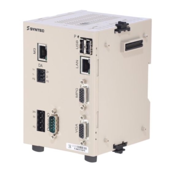
FC-Serial Axis Controller
Basic Installation Instructions
Dear users, please go through the instructions in detail before the installation.
Also, please hand the manual to the actual operator of the machine and preserve it
properly.
CNC controllers are precision electronic devices. For the safety of both operators
and the machine, please ensure all installations, tests, and adjustments are operated
by professional personnel. For the description with "DANGER", "WARNING"
and "CAUTION" in the manual, please read them in detail. If there are any
concerns, please contact our branches in your region. Our professionals are glad to
be at your service.
The following are the guidelines you should comply with before finishing
reading the complete manual:
⚫
The installing environment should be indoor and without water vapor,
corrosive or flammable gas.
⚫
Implement the wirings according to the wiring diagram.
⚫
The grounding must be strictly implemented and follow the current National
Electrical Code. (References: NFPA 70: National Electrical Code,2005 Ed.)
⚫
Do not modify the wirings while the device is powered up.
Applicable Types
Type
Product Name
1
F31-FC-C
FC-Serial Axis Controller
2
F31-FC-B-600WA
FC-Serial Axis Controller
3
F31-FC-B-710CA
FC-Laser Cutting Controller
Safety Precautions
1.
Please pay extra attention to the instructions below while operating the product.
◼ Please install the controller according to the manual or it may cause
damage to the equipment.
◼ Do not operate the product in places exposed to water vapor, corrosive, or
flammable gases. It may cause damage to the device, electric shocks, fire,
or explosion.
◼ Do not install the product at a temperature exceeding the specified range.
It may cause device damage or malfunctioning.
◼ The controller series is designed to control the motor of the machine tool
and manage the IO control. Do not touch the internal circuits or
components while the controller is powered up. It may cause electric
shock or device damage.
◼ The internal circuit board of the driver contains CMOS ICs, which are
vulnerable to static electricity. Do not touch the circuit board with your
hands before taking any precautions.
◼ The product has been tested and found to comply with the limits for a KC
B01-FC-C-03
Class A Commercial equipment) digital device. It was for use in
commercial and industrial environments instead of households.
◼ Do not apply the product to machines that may lead to casualties, device
V1.1
damage or system shut down.
◼ Please cut off all the external loads when powering up the
controller for the first time. The built-in testing PLC program may
start the motor immediately after power-up, which may be
dangerous for the staff around.
◼ The controller is a precision instrument. Please prevent
non-maintenance staff or non-professional electronic control
personnel from disassembling the device.
◼ Please apply the correct ground loop to prevent errors from the
controller.
◼
Please separate the communication cable of the driver from all the
other motor and power cables with individual wiring ducks to
prevent the controller from malfunction caused by loud noise
interference.
◼ The CNC controller adopts a microcomputer design. Please install
the controller in a safe area and keep it clean. Please keep iron
shavings, wires, water, corrosive gas, and liquid from the driver to
avoid malfunction.
◼ Storage temperature range: -20℃~60℃
Storage relative humidity range: 0% to 90% and without
condensation.
◼ Operating temperature range: -10℃~55℃
Please reserve at least 50mm in width for ventilation and heat
dissipation.
◼ The grounding of the controller and machine tool system is
necessary for leakage protection and prevention of lightning
strikes. Please ensure the driver and the machine tool system are
grounded properly before installing.
◼ The rated voltage of the controller power system should not exceed
DC18~32V. If the operating environment provides an unstable
voltage source, please apply a voltage stabilizer so that the
controller can function properly.
◼ Please turn off the power before plugging/unplugging the cables or
modifying the wirings to prevent electric shocks or damage to the
driver.
◼ Please ensure all the terminals are in the correct positions while
wiring to prevent the driver from damage caused by wiring
mistakes.
◼ Do not touch the terminals within 10 minutes after cutting off the
power in case the residual voltage may cause electric shocks.
◼
Do not touch the panel with sharp objects or it may cause
malfunction due to depression.
◼
To ensure communication quality, the length of USB extension
cords in use shall not exceed five meters. Besides, do not charge or
supply
malfunction.
power via the USB port; otherwise, it may cause controller
2.
Wiring Notifications
Each FC controller can connect up to 10 sub-modules.
When more sub-modules are needed, please purchase the FC-PWR module and
connect according to the Basic Wiring Diagram.
MPG terminal's +5V output capacity is 200mA and is only for a single external MPG.
Do not connect it to other loads or it may cause errors due to the lack of driving
force.
The attached DC24V power adapter is only for the FC main module.
Please use additional supplies to provide DC24V power of sub-modules and I/Os
since sharing the same supply with main modules may cause interference.
The external DC24V power supply used in wiring should be certificated and
protective to avoid the malfunction due to wiring mistakes. (Recommendation
standard:fulfill requirements of both EN60950 & UL1950)
Please crimp or weld the wire connections while doing the wirings.
When using a solenoid valve or other inductive loads, please apply an arc
extinguisher or an RC varistor to ensure the life of the contact points. Advantages of
the arc extinguisher:
1) Extend the life of electrical contacts.
2) Reduce the sparks from the contact points.
3) Restrain the impulse voltage.
4) Prevent the inductive loads from interferences caused by back EMF.
In case of the use of Ethernet, to prevent internet congestion and noise, the CAT5e or
CAT6 cable is recommended.
To avoid noise interference, it is recommended to use Syntec standard SRI cables to
connect to Syntec controllers. As for the cables connecting to other FC modules,
shielded twisted pairs are recommended.
Please connect the ground wire to class-3 (under 100Ω). Poor grounding may cause
signal errors, electric shock, or fire.
Do not connect other cables to extend the original length. It may cause signal errors
or malfunction.
If the servo line in use is not a standard Syntec cable, please verify all the terminals
are connected properly before power-on. Incorrect wirings will lead to controller
output command errors and malfunctioning.
Grounding Directions:
1)
The guide rail of FC Controller sets must be grounded.
2)
The length of grounding wires should comply with the electrical equipment
regulations; the shorter the better.
3)
Ground the grounding wire of the driver separately with high-current loads such
as electric welders or high-frequency motors.
4)
Please refer to the pictures below when the controller is grounded with multiple
electrical control devices. Do not make it a loop.
(a) O
(b) O
(a) 良
(b) 良
(c) X
(c) 不良
Advertisement
Table of Contents

Related Manuals for Syntec F31-FC-C


Summary of Contents for Syntec F31-FC-C
- Page 1 If the servo line in use is not a standard Syntec cable, please verify all the terminals controller can function properly. are connected properly before power-on. Incorrect wirings will lead to controller Safety Precautions ◼...
- Page 2 (Side View) Basic Wiring Diagram Cover Plate Serial Servo FG (grounding) motor USB Arrangement I/O equipment monitor DO module Di module Syntec adapter load power Floating Ground (Right) MPG Connector Arrangement SIGNAL SIGNAL SIGNAL M3 Port Connect to the driver of the M3 Communication Interface...
Need help?
Do you have a question about the F31-FC-C and is the answer not in the manual?
Questions and answers