Advertisement
Quick Links
M3-81RA/D/S/G-MPG
7-inch Teach Pendant Controller
Basic Installation Instructions
Dear users, please go through the instructions in detail before the installation. Also, please hand the
manual to the actual operator of the machine and preserve it properly.
CNC controllers are precision electronic devices. For the safety of both operators and the machine,
please ensure all installations, tests, and adjustments are operated by professional personnel. For the
description with "DANGER," "WARNINGS," and "CAUTIONS" in the manual, please read them in
detail. If there are any concerns, please contact our branches in your region. Our professionals are
glad to be at your service.
The following are the guidelines you should comply with before finishing reading the complete
manual:
⚫
The installing environment should be indoor and without water vapor, corrosive or flammable
gas.
⚫
Implement the wirings according to the wiring diagram.
⚫
Implement the grounding strictly and follow the current National Electrical Code.
(References: NFPA 70: National Electrical Code,2005 Ed.)
⚫
Do not modify the wirings while the device is powered up.
1.
Safety Precautions
Please pay extra attention to the instructions below while operating the product.
◼
Please comply with the manual when installing the teach pendant, and please
connect to the controller slot of the matching teach pendant. Do not connect the
connector to compatible ports of unknown motors, or it may cause malfunction to
the teach pendant due to an abnormal power supply.
◼
Please cut off all the external loads when powering up the teach pendant for the
first time. The built-in testing PLC program may start the motor immediately
after power-up, which might be dangerous for the staff around.
◼
Do not operate the product in places exposed to water vapor, corrosive, or
flammable gases. It might cause damage to the device, electric shocks, fire, or
explosion.
◼
Do not install the product at a temperature exceeding the specified range. It
might cause device damage or malfunctioning.
◼
The product has been tested and found to comply with the limits for KC Class A
Commercial equipment) digital device. It was for use in commercial and
industrial environments instead of households.
◼
Do not apply the product to machines that might lead to casualties, device
damage or system shut down.
◼
The teach pendant is a precision instrument. Please prevent non-maintenance
staff or non-professional electronic control personnel from disassembling the
device.
◼
Do not touch the teach pendant and the panel with sharp objects. Doing so may
cause damage to the appearance of the teach pendant or the panel.
◼
Please apply the correct ground loop to prevent errors from the controller.
◼
The teach pendant adopts a microcomputer design. Please install the teach
pendant in a safe area and keep it clean. Please keep iron shavings, wires, water,
corrosive gas, and liquid from the teach pendant to avoid malfunction.
B01-M3-81R-MPG-03
◼
Storage temperature range: -20℃~60℃
Storage relative humidity range: 0% to 90% and without condensation.
◼
Operating temperature range: -10℃~55℃
Please ensure that there are proper ventilation and heat dissipation area before
operating.
◼
The grounding of the teach pendant and machine tool system is necessary for
leakage protection and prevention of lightning strikes. Please ensure the teach
V1.1
pendant and the machine tool system are grounded properly before installing.
◼
The rated voltage of the teach pendant power system should not exceed 5±5%V.
If the operating environment provides an unstable voltage source, please apply a
voltage stabilizer so that the controller can function properly.
◼
Please turn off the power before plugging/unplugging the cables or modifying the
wirings to prevent electric shocks or damage to the teach pendant.
◼
Do not fold the wire of the teach pendant and connectors vigorously, or it may
cause internal damage to the wire or contact disconnected.
◼
Please make sure all the terminals are in the correct positions while wiring to
prevent the driver from damage caused by wiring mistakes.
◼
Do not touch the terminals within 10 minutes after cutting off the power in case
the residual voltage might cause electric shocks.
2.
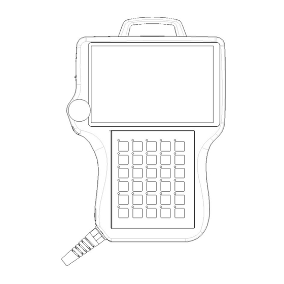
Controller Interface Specifications
(Teach pendant & Transfer Module: Front View)
A
7-inch Screen
Key
B
C
MPG
D
Teach pendant Cable
Teach pendant
E
Dedicated Connector
Emergency Stop
K
Button
F
Power Indicator Light
Display Window
Edit
Fine Tuning Control
10/17m cable
Functions Included:
1. The Internet interface
2. 24V
Rated Current 300mA
3. 0V
4. The SRI interface
The M3 interface
For emergency stop
Indicate the power condition
G
LAN
Connect to the Internet
H
M3
M3 serial signal interface
I
HHB
Connect to the palmtop controller
J
24V Power Input
DC 24V‧1A Power input
(Rear View: Teach pendant)
C
A
USB Port
Connect to the USB
B
Wrist Band
Handheld
C
Key Switch
For unlocking word keys
(Side View: Transfer Module)
Connect to the upper fastener of other FC
A
Upper Fastener
function modules
Internal
Signal
Connect to other FC function modules for
B
Connector (R)
communication
C
Slide Tenon Batch
Control the batch of the slide tenon
Connect to the lower fastener of other FC
D
Lower Fastener
function modules
E
Slide Tenon
Fix the tenon on the slide
A
B
Advertisement

Related Manuals for Syntec M3-81RA/D/S/G-MPG


Summary of Contents for Syntec M3-81RA/D/S/G-MPG
- Page 1 Storage temperature range: -20℃~60℃ 24V Power Input DC 24V‧1A Power input Storage relative humidity range: 0% to 90% and without condensation. M3-81RA/D/S/G-MPG ◼ Operating temperature range: -10℃~55℃ Please ensure that there are proper ventilation and heat dissipation area before (Rear View: Teach pendant)...
- Page 2 Do not connect other cables to extend the original length. It might cause signal errors or malfunction. If the servo line in use is not a standard Syntec cable, please verify all the terminals are connected properly before power-on. Incorrect wirings will lead to controller output command errors and malfunctioning.
- Page 3 The +5V power capacity provided by the MPG terminal is 200mA, which is only for a single external MPG. Do not connect to any inductive loads or it might lead to the interference of the controller and cause malfunctioning. ...
Need help?
Do you have a question about the M3-81RA/D/S/G-MPG and is the answer not in the manual?
Questions and answers