Advertisement
Quick Links
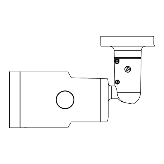
This guide is for quick installing and connecting the G-Cam/HWPC-1450 Bullet IP Camera. For more details,
please refer to the User's Manual.
Installation Notices
• This camera must be installed by qualified personnel and the installation should conform to all local codes.
• Do not replace batteries of the camera. Risk of explosion may occur if the battery is replaced by an incorrect type.
• To use an external power supply, please contact the camera manufacturer to confirm that the power supply
complies with the LPS requirements and shares the same power specifications with the camera.
All-in-One Cable
No.
Connector
Pin
1
RJ-45
-
Green
2
Audio I/O
Pink
3
BNC*
-
1
2
Alarm I/O
4
3
(5-pin Terminal Block)
4
5
Power (DC 12V / AC 24V)
1
5
(2-pin Terminal Block)
2
(*) optional
Desiccants Removal
Before installation, remove the desiccants on the vent at the bottom of the camera body. The location of the
desiccants is shown below.
G-Cam/HWPC-1450 Bullet IP Camera Quick Guide
Definition
Remarks
For network and PoE connections
Audio Out / Mic Out
Two-way audio transmission
Audio In / Mic In
For analog video output
Alarm In 2+
Alarm connection
Alarm In -
Alarm In 1+
#Do NOT connect external power
Alarm Out -
supply to the alarm I/O connector.
Alarm Out +
DC 12V −
AC 24V 1
Power connection
DC 12V +
AC 24V 2
microSD Card Slot / Default Button
The positions of microSD card slot and default button are shown as below.
microSD Card Slot
Insert the microSD card into the card slot to store videos and snapshots. Do not remove the microSD card when the
camera is powered on.
NOTE: It is not recommended to record with the microSD card for 24/7 continuously, as it may not be able to
support long term continuous data read/write. Please contact the manufacturer of the microSD card for
information regarding the reliability and the life expectancy.
Default Button
Press the default button with a proper tool for at least 1 seconds to restore the
system.
Camera Cabling
Please follow the instructions below for cable connections.
Power Connection
Please use a DC 12V / AC 24V adaptor and connect it to the 2-pin terminal block of the All-in-One cable and the
power outlet. Alternatively, connect the Ethernet cable to the RJ-45 connector of the All-in-One cable, and plug the
other end of the cable to a Power Sourcing Equipment (PSE) switch.
Ethernet Cable Connection
Connect one end of the Ethernet cable to the RJ-45 connector of the All-in-One cable, and plug the other end of the
cable to the network switch or PC.
NOTE: In some cases, Ethernet crossover cable might be needed when connecting the camera directly to the
PC.
NOTE: Check the status of the link indicator and the activity indicator LEDs. If the LEDs are unlit, please
check the LAN connection.
Green Link LED indicates good network connection.
Orange Activity LED flashes for network activity indication.
NOTE: The ITE is to be connected only to PoE networks without routing to the outside plant or equivalent
description.
Advertisement

Related Manuals for Geutebruck G-Cam HWPC-1450


Summary of Contents for Geutebruck G-Cam HWPC-1450
- Page 1 G-Cam/HWPC-1450 Bullet IP Camera Quick Guide This guide is for quick installing and connecting the G-Cam/HWPC-1450 Bullet IP Camera. For more details, microSD Card Slot / Default Button please refer to the User’s Manual. The positions of microSD card slot and default button are shown as below. Installation Notices •...
- Page 2 Initial login to the IP camera The first time you access the IP camera, you will be asked to change your password. You must perform this step in order to continue. NOTE: Passwords must be at least 12 characters long, with an uppercase letter, a lowercase letter, numeric character and a special character ~@#$%^&*_-+=:;<>...
Need help?
Do you have a question about the G-Cam HWPC-1450 and is the answer not in the manual?
Questions and answers