Table of Contents
Advertisement
Advertisement
Table of Contents

Related Manuals for Geutebruck G-Cam/E2 Series


Summary of Contents for Geutebruck G-Cam/E2 Series
- Page 1 G-Cam/EWPC-2275 Full HD IR Bullet IP Camera Installation...
-
Page 2: Preface
G-Cam/E2 Series Installation Preface The information given in this manual was current when published. The company reserves the right to revise and improve its products. All specifications are subject to change without notice. Copyright Under copyright laws, the contents of this user manual may not be copied,... -
Page 3: Regulation
G-Cam/E2 Series Installation Regulation This device complies with Part 15 of the FCC Rules. Operation is subject to the following two conditions: (1) This device may not cause harmful interference, and (2) this device must accept any interference received, including interference that may cause undesired operation. -
Page 4: Warnings And Cautions
G-Cam/E2 Series Installation Warnings and Cautions Handle the camera carefully Do not abuse the camera. Avoid striking, shaking, etc. The camera could be damaged by improper handing or storage. Installing electricity wiring carefully Ask qualified personnel of electrical wiring for the installation. Please note the technical specifications for correct power supply at the end of this manual. -
Page 5: Table Of Contents
G-Cam/E2 Series Installation Table of Contents Preface ..........................2 Regulation ........................3 Warnings and Cautions ....................4 Table of Contents ......................5 1. FEATURES ......................... 6 2. PACKAGE CONTENTS ....................7 3. PART NAMES ......................8 ... -
Page 6: Features
G-Cam/E2 Series Installation 1. FEATURES Camera 1/2.9” 1080p CMOS Sony STARVIS Image Sensor True Day / Night DC Auto Iris Lens Embedded IR Illuminator Remote Zoom/Focus Control (One Click AF) Weather proof (IP66) Video H.264 Baseline, Main, High Profile (MPEG-4 Part 10/AVC), MJPEG (Motion JPEG) -
Page 7: Package Contents
G-Cam/E2 Series Installation 2. PACKAGE CONTENTS Please unpack the package carefully and handle the equipment with care. The packaging contains: Camera DC Power Adaptor & Plugs Screws (M4x30) and Plastic Anchors Hex Wrench (3mm) Video Output Cable Silicon Waterproof Band... -
Page 8: Part Names
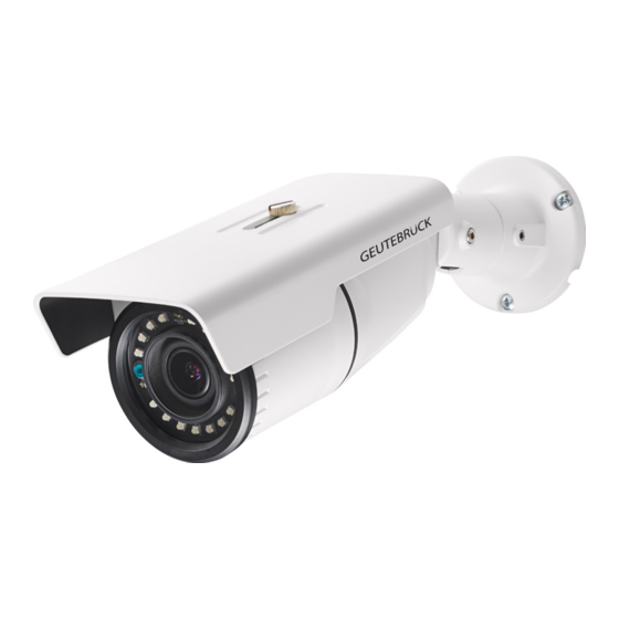
G-Cam/E2 Series Installation 3. PART NAMES ① ⑥ ⑧ ⑦ ⑤ ④ ② ③ * Models herein and their appearance are subject to change without any prior ① Sunshield ② Video Out Cable socket Socket for the video output cable included in the package (CVBS: 1.0Vp-p / 75Ω BNC) ③... -
Page 9: Installation
G-Cam/E2 Series Installation 4. INSTALLATION 4.1. Installing the camera 4.1.1. Installation without bracket Installation Template (Unit: mm) Installation template’s image size scale in this installation guide is not 1:1. The correct-size template design paper can be found inside the package se... - Page 10 G-Cam/E2 Series Installation 1) Place the installation template included in the package on the desired installation surface. 2) Drill three holes in correct positions based on the template paper, and insert the anchor blocks into the holes. 3) Attach the silicon waterproof band included in the package to the camera’s...
- Page 11 G-Cam/E2 Series Installation Installation of Ferrite Core Installing the ferrite core is highly recommended to reduce high frequency noise level. The instructions and the image below explain how to install the ferrite core on the cable. 1. Open the ferrite core by lifting the clip.
-
Page 12: Compatible Accessories
G-Cam/E2 Series Installation 4.1.2. Compatible accessories - 5.02071: G-Cam/EBFC-002 (in-ceiling adapter for outdoor fixdome) - 5.02072: G-Cam/EBWM-001 (Wall mount bracket for E2 EFD) in comb. with 5.02083, G-Cam/ECMA-002 corner mount adapter or 5.02082, G-Cam/EPMA-004 Pole mount adapter) - 5.02080: G-Cam/EBWM-005 (Wall mount bracket for E2) with adapter 5.02085, G-Cam/EBDA-200 only. -
Page 13: Adjusting Angle Of The Camera
G-Cam/E2 Series Installation 4.2. Adjusting angle of the camera 1. Adjust the camera to the desired angle by unscrewing the joints referring to the following pictures. Adjust the joint to Adjust the joint to Adjust the joint to tilt install the camera on delicately the camera angle. -
Page 14: Adjusting Zoom And Focus
G-Cam/E2 Series Installation 4.3. Adjusting zoom and focus To be able to adjust zoom and focus, it is necessary to connect the device to a network. Please refer to 6.CONFIGURATION for the detailed method of network connection. Once the device is on the network and the webpage is open, go to Setup> Video & Audio >... -
Page 15: Setting The Image Attributes
G-Cam/E2 Series Installation 4.4. Setting the Image Attributes On the camera’s webpage, users can configure the image attributes. The menu of the image attributes is available at “Video Appearance” via the path Setup > Video & Audio > Camera. The following features can be adjusted: Brightness, Contrast, Saturation, and Sharpness. -
Page 16: Connections
G-Cam/E2 Series Installation 5. CONNECTIONS BLACK: AUD IN ① BROWN: AUD GND RED: AUD OUT ② ORANGE: DI YELLOW: DI COM ③ GREEN: DO1 (N.O) ④ ⑤ BLUE: DO1 COM ① Audio Connection The camera provides a mono audio input and output. Due to low audio output power, an amplified speaker is recommended for enhanced sound (Refrain from connecting a headphone or an earphone directly to the camera). - Page 17 G-Cam/E2 Series Installation Sensor (DI) connection Sensor (DI) can be connected to either a voltage type sensor or a relay type sensor. Settings can be done through the camera’s webpage. Input voltage range: 0VDC minimum to 5 VDC maximum, max. 50mA.
- Page 18 G-Cam/E2 Series Installation ③ LAN connection This is a RJ45 LAN connector for 10/100 Base-T Ethernet. Use the Ethernet cable (RJ45) to connect the device to a hub or a router in the network. When the device is connected in network, the orange LED blinks while green LED .
-
Page 19: Configuration
G-Cam/E2 Series Installation 6. CONFIGURATION 6.1. Set up network environment The default IP address of the device is 192.168.XXX.XXX. Users can identify the IP address of the device from converting the MAC address’s hexadecimal numbers, which is attached to the device. -
Page 20: Custom Ip Environment
G-Cam/E2 Series Installation Custom IP Environment IPAdminTool is a management tool, which automatically scans all network products for users to perform administrative tasks, which includes network configurations, firmware update, device reboot, and device organizations. To modify the device’s default IP address for customized network area: 1. -
Page 21: View Video On Web Page
G-Cam/E2 Series Installation 6.2. View video on web page Type in the proper IP address to view the live streaming images. For first access this window may open: 1. When the browser asks to install the AxUMF software, click Install to proceed. - Page 22 G-Cam/E2 Series Installation 3. The IP camera´s IP address will be inserted into the web browsers´s input box. This page opens after clicking on “Setup” on the home page. Whether directly accessing the streaming video by typing the IP address on a web page or taking steps through IPAdminTool, ActiveX is needed to be installed for Microsoft®...
-
Page 23: Reboot
G-Cam/E2 Series Installation 6.3. Reboot Perform the following procedures to reset your device. On the camera 1. Press the reset button for 2 seconds when the device is powered on. 2. Wait for the system to reboot. Do not press the reset button for more than 2 seconds. Otherwise, the camera may be switched to its factory default settings. -
Page 24: Factory Default
G-Cam/E2 Series Installation 6.4. Factory Default Resetting the device back to the factory default will initialize all the parameters of the device. However, the factory default on the webpage allows certain main parameters to be preserved. On the camera 1. Press the reset button for 10 seconds by making sure that booting is complete on the device. -
Page 25: Safe Mode
G-Cam/E2 Series Installation 6.5. Safe Mode There may be certain occasions that your camera repeatedly fails to boot. Then, your camera may enter safe mode to be recovered from the occasions. What may have caused Safe Mode? Here below are the main typical causes: * The power supply is continually unplugged certain times in the middle of system booting. -
Page 26: Configuration In Geutebrück Gscsetup
G-Cam/E2 Series Installation 6.6. Configuration in GEUTEBRÜCK GscSetup Start the software "GscSetup" by double clicking on the desktop icon. Double click on "local" (1). Click on "Hardware" (2). The “Hardware module list” will open. With a right click on "Hardware module list" (1) you will open a pop up window. - Page 27 G-Cam/E2 Series Installation Click here also on Button "Add". A list with the available hardware modules opens (see following figure). Please scroll to the camera Plugin <E2 IPC> (32) and doubleclick on it. The chosen module (1) appears as "IP-Camera Plugin 001" in the "Hardware module list" (see next figure).
- Page 28 G-Cam/E2 Series Installation Now you must assign a media channel to transmit the camera’s pictures. Please click in "General settings" on the menu item "Media channels" (1). A list of the available media channels appears. Click the icon "Add" (2) on the toolbar to add a new media channel.
-
Page 29: Advanced Configuration
G-Cam/E2 Series Installation 6.4.1. Advanced configuration In the hardware configuration you can make advanced settings like the streaming behaviour (see following screenshots). Please note, that the configurations made here will overwrite the webbrowser configurations! PTZF Move doesn’t apply to Box cameras. - Page 30 G-Cam/E2 Series Installation Click the icon on the toolbar to send your choice to the server. Please note, that the configurations made here will overwrite the webbrowser configurations! Close the GSCSetup software. Start the GSCView software with a double click on the desktop icon GSCView.
-
Page 31: Configuration In Geutebrück G-Set
G-Cam/E2 Series Installation 6.7. Configuration in GEUTEBRÜCK G-Set NOTE: For correct installation of IP cameras one Option G-Core/CamConnect must be available for each camera. Available options are shown in G-Set at General settings - Options. Required options can be ordered using General settings - Options in G-Set. - Page 32 G-Cam/E2 Series Installation Right clicking this URL opens a menu in which the URL can be copied, saved or opened in the default browser. After passing the URL to a browser, follow the instructions on the GEUTEBRÜCK website. Adding IP Cameras Please double click at desktop on the G-Set icon to open the G-Set configuration menu.
- Page 33 G-Cam/E2 Series Installation The Media Channel Wizard automatically searches for existing network cameras and displays them in the first column. Cameras for which access rights are available are also displayed with a small camera image. You can now select the desired camera by clicking the tick box (changes to green) and edit the general information and the camera-specific data.
- Page 34 G-Cam/E2 Series Installation Step 3: Summary (check settings, confirm and transfer settings to the server). Mouse click on tab Summary provides you with an overview of all the settings that have been defined for your cameras. Please confirm your settings by clicking the button Save & Finish.
-
Page 35: Appendix (A): Specifications
G-Cam/E2 Series Installation APPENDIX (A): SPECIFICATIONS Image sensor (Chip) 1/2,9“ CMOS (SONY Starvis Exmor R) Picture format 16:9, 4:3 Scanning system Progressive scan Mega pixel 2 MP (Full HD) Minimum sensitivity 0.2 Lux (color), 0 Lux (B/W; IR LEDs on) -
Page 36: Appendix (B): Power Over Ethernet
G-Cam/E2 Series Installation APPENDIX (B): POWER OVER ETHERNET The Power over Ethernet (PoE) is designed to extract power from a conventional twisted pair Category 5 Ethernet cable, conforming to the IEEE 802.3af Power-over-Ethernet (PoE) standard. IEEE 802.3af allows for two power options for Category 5 cables. -
Page 37: Appendix (C): Dimensions
G-Cam/E2 Series Installation APPENDIX (C): DIMENSIONS (Unit: mm) -
Page 38: Appendix (D): Hexadecimal-Decimal Conversion Table
G-Cam/E2 Series Installation APPENDIX (D): HEXADECIMAL-DECIMAL CONVERSION TABLE Refer to the following table when you convert the MAC address of your device to IP address. - Page 40 GEUTEBRÜCK GmbH Technische Änderungen vorbehalten. Im Nassen 7-9 | D-53578 Windhagen Tel. +49 (0)2645 137-0 | Fax-999 Technical alterations reserved. Sous réserve des modifications. info@geutebrueck.com Suministro sujeto a modificaciones técnicas o disponibilidad. www.geutebrueck.com...
Need help?
Do you have a question about the G-Cam/E2 Series and is the answer not in the manual?
Questions and answers