Kinetico premier Compact 2900 0138 Manual
- Installation and user manual (60 pages) ,
- User manual (20 pages) ,
- Installation and user manual (20 pages)
Advertisement
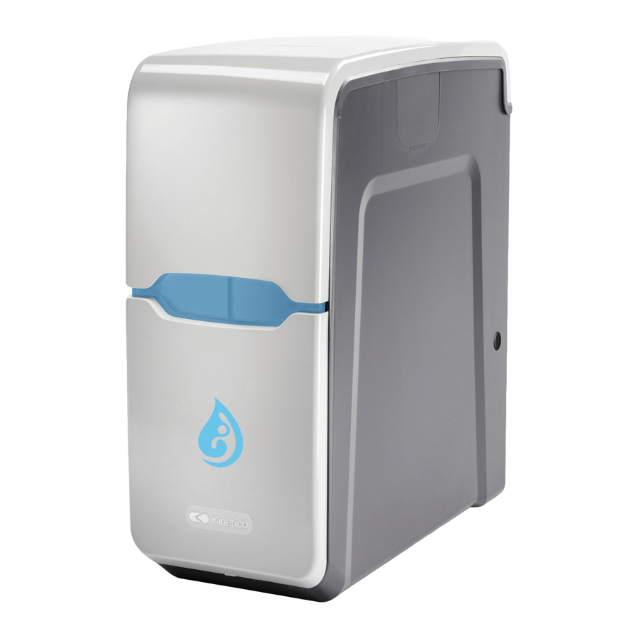
Contents of box
Identify the following parts before proceeding.

Specifications
| Meter Disc | 1 | 2 | 3 | 4 | 5 | 6 | 7 | 8 | ||
| Max hardness | PPM | 62 | 124 | 184 | 244 | 309 | 380 | 448 | 513 | |
| ˚dH | 4 | 8 | 11 | 15 | 19 | 23 | 27 | 30 | ||
| ˚TH | 6 | 13 | 18 | 25 | 32 | 38 | 45 | 51 | ||
| Litres between regenerations | 1961 | 980 | 654 | 490 | 392 | 327 | 280 | 245 | ||
| Cabinet dimensions (h x w x d) | 498 x 219 x 468 mm |
| Salt used per regeneration | 0.34 kg |
| Regeneration time | 11 minutes |
| Flow rate @ 1 bar pressure drop | 22.7 l/min |
| Pipe connections - in/out | ¾" BSP |
| Min/max operating pressure | 1.8 - 6 bar |
| Min/max operating temperature | 2 - 24˚C |
Getting to know the softener

Pre-installation check list
When determining the location of the softener, the following should be considered:

Installation will vary but should consist of:
- pressure regulating valve on the water supply to the softener where the incoming pressure exceeds 6 bar.
- non-return valve on the mains water supply to the softener. If using a Kinetico supplied installation kit, a non-return valve is built into the inlet tee.
- by-pass assembly which enables the softener to be isolated from the water supply for maintenance and service. This also maintains the water supply when the system is disconnected.
- drain line from the softener to a waste pipe through an appropriate air gap. The drain must comply with local plumbing codes.
- An overflow run to a suitable outlet that is visible.
Ensure you have the following:
- Kinetico blending by-pass valve plus a single check valve.

Or, a means of constructing a by-pass which consists of: 3 valves, Tee pieces, Single check valve

- Connections for the inlet and outlet, either by means of flexible pressure rated hoses or by direct pipework. Connections on the softener and the Kinetico blending by-pass valve are 3/4" BSP male threaded fittings.
- 1/2" ID hose for both the overflow and the drain.
- Jubilee clip for the drain line.


Installation instructions
- Locate:
- Ensure the unit can be positioned on a flat surface.
- If sand, silt or turbidity are present in the water supply, a pre-filter should be installed before the water softener.
Please note: For ease of installation the softener can be installed with the connections on the left or right side of the cabinet by reversing the components.

- Insert blanking plate:
Insert the blanking plate into the outlet which is not in use.
Lift up into position, then drop the plate down into the slot.

- Test water pressure:
Test incoming pressure to the unit. A pressure regulating valve will be required if the pressure is above 6 bar.

- Install:
Plumb pipework as necessary to accommodate a by-pass assembly, h 105mm x w 194mm x d 80mm.

Or, establish a by-pass installation based on the following diagram.


Do not solder any fitting while connected to the unit adaptors.
Care should be taken during the installation process to ensure solder and flux do not come in contact with any of the components.
- Flush:
After plumbing is complete, but before connecting to water softener, flush both inlet and outlet lines and allow water to rinse out any debris. - Remove cardboard:
Ensure all cardboard is removed from the inside of the softener.- Remove top lid and support bar.
- Carefully remove the two pieces of cardboard, then replace the support bar and lid.
- Fit inlet/outlet connection:
When using the Kinetico blending by-pass valve, consult separate installation instructions. Please note, the orientation of the valve will determine which connection is used as the inlet. Or, follow the process below:- Fit 2 o-rings to each in/out adaptor then lubricate with the supplied silicone grease.

- Connect inlet/outlet adapters to supply and return hoses remember to use the washers.
- Install adapters into control valve in/out ports, ensuring that they are fitted into the correct ports (see flow arrows on valve for reference).
- Attach the retaining bracket and pin to the control valve.
- Fit 2 o-rings to each in/out adaptor then lubricate with the supplied silicone grease.
- Run drain line:
- Run a drain line to a discharge point, checking for any obstructions or possible kinks.
FOLLOW LOCAL PLUMBING CODES.

- Before connecting the drain line to the unit, slide on the stainless steel jubilee clip.
- Push the drain line onto the barbed fitting and tighten the jubilee clip securely.
- Run a drain line to a discharge point, checking for any obstructions or possible kinks.


Please note:
Drain lines must not run more than 2.4m up or exceed a total of 9m. The drain line must not be restricted or kinked.
Review
- Pressure:
If a pressure regulating valve has been fitted, ensure it has been correctly set to 6 bar. - Drain line:
Ensure the drain line is securely attached, has no restrictions or kinks, uses an airgap and is fully compliant. - Overflow:
Ensure the overflow has no kinks, is securely attached and that water is able to fall away with gravity. - Inlet/Outlet connections:
Ensure the hoses/plumbing are attached securely, using the washers provided, and are firmly held in place using the retaining bracket and pin. - By-pass assembly:
Ensure the assembly is in the "by-pass" position.


Commissioning instructions
- Pressurise:
With the water to the property restored, slowly move the assembly to the "in service" position. Water may run to drain until the unit is fully pressurised. - Fill the brine tank with water:
Allow the brine tank to fill with water until the brine valve shuts off. The water level should be approximately 25mm over the grid plate. TIP: If the cabinet does not fill with water please refer to the "Useful Information" section.

- Initiate a backwash:


- Using a Phillips head screwdriver push down on the actuator, and slowly turn CLOCKWISE until the indicator dot reaches the letter W in the word "BACKWASH" on the clear cap.
- You will hear a rush of water and air going to the drain.
- When the cycle has finished (approx 4 mins), repeat the procedure, turn the indicator dot to the next backwash cycle and allow to finish (approx 4 mins).
- Add salt:
For convenience, the water softener has been designed to accommodate both block and tablet/pellet salt.
Block Salt:
To use salt blocks, simply place them in the salt compartment with the indents facing forwards.

Tablet and Pellet Salt:
Simply pour into the salt compartment.
![]()
Only use salt manufactured for use in water softeners. Do not use rock or granular salt in your system. They contain impurities that can interfere with performance and could invalidate the Limited Warranty. - Fit the lid:
Replace the lids and check plumbing for any leaks. The installation is now complete.


Useful information
- Should water be present in the salt compartment?
Yes, it is normal to see water at a level of 25mm above the salt grid. If water is not present to this level:- Fill the salt bay with water until the level is 25mm above the salt grid. Then conduct a manual regeneration.
- To manually regenerate using a Phillips head screwdriver push down on the actuator, and slowly turn CLOCKWISE ONLY until the actuator tab has advanced the indicator dot to the word "BRINE".
- You will hear a rush of water and air going to the drain.
- When the vessel has finished its cycle (approx 12 mins), repeat the procedure, advance the indicator dot to the word "BRINE" in the next section and allow to finish (approx 12 mins).

- How do I correct the water level if it sits higher than the recommended 25mm above the salt grid?
Check that the brine valve is correctly held in place by the support bar and is seated firmly on the base of the cabinet.

- Why am I experiencing varying levels of hardness?
The softener will provide soft water immediately; however, until mains water has been displaced from the pipework, storage tanks and hot water system, you will experience varying degrees of hardness.
Depending on your water system and water usage, this may take a few weeks to clear.
It is also advisable to check that the by-pass valve is closed, when not using the Kinetico blending by-pass valve.


Safety information
Read all information carefully prior to installing and using the water softener.
Qualified Installer

Kinetico recommends that a qualified installer performs the installation. Failure to install the system as instructed could invalidate the Limited Warranty.
Water Pressure

Do not install if the supply water pressure exceeds 6 BAR (87 psi), unless a suitable pressure regulating valve has been installed on the softener water supply.
Water Temperature

Do not install the Kinetico softener in an area where the water temperature can exceed 24°C or cause the unit to freeze. Freezing temperatures will damage the system.
Overflow

Where a cabinet overflow could cause damage, you must install a 1/2" I.D. hose to the barbed fitting on the cabinet and run to a suitable outlet that is visible and capable of taking the overflow (i.e. through the outside wall).
Make sure the hose does not go higher than the barbed fitting as the water will flow away using gravity.
Copper/Plastic Pipework

Where copper/plastic pipework is used, Kinetico advises adherence to the regulatory requirements to ensure adequate earth bonding is provided.
Intended Use

Not intended to be used for treating water that is micro-biologically unsafe or water that has an unknown quality, without adequate disinfection before or after the system.
Conform to Regulations

You must ensure that the installation conforms to local plumbing codes and regulations. Note: Refer to separate instructions for important WQA certification information.
Plumbing Schematic

Please refer to the plumbing schematic before commencing an installation.
Documents / ResourcesDownload manual
Here you can download full pdf version of manual, it may contain additional safety instructions, warranty information, FCC rules, etc.
Advertisement


Need help?
Do you have a question about the premier Compact and is the answer not in the manual?
Questions and answers