
Related Manuals for Miele Steelco ID 300/1


Summary of Contents for Miele Steelco ID 300/1
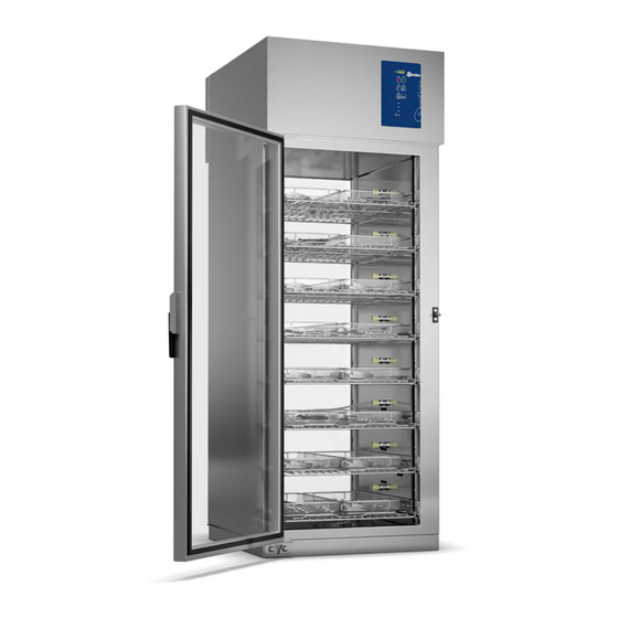
- Page 1 Instructions Manual User Manual INSTRUMENT DRYING CABINET ID 300/1 ID 300/2 Serial N°:...
- Page 2 Via Balegante, 27 31039 Riese Pio X (TV) ITALY Manufacturer: STEELCO S.p.A. Via Balegante, 27 31039 Riese Pio X (TV) ITALY 12/12/2022_REV.1.22_COD.ID300019_A4 PAG.
-
Page 3: Table Of Contents
CONTENTS GENERAL RULES ............................. 6 ’ ........................6 IMITS OF MANUFACTURER S LIABILITY ....................6 ANUAL VALIDITY CONTENTS AND CONSERVATION ................................ 7 EGULATIONS SAFETY INFORMATION ........................... 8 ........................8 NTENDED PURPOSE IMPROPER USE ........................ 9 MPORTANT WARNINGS AND SUGGESTIONS ........................... 9 AFETY RECOMMENDATIONS ................. - Page 4 PROCEDURE OF RESET ........................28 SPECIAL FEATURES ..........................28 ..............................28 OWER FAILURE WORK PROCEDURES ........................29 10.1 ..............................29 NTRODUCTION 10.2 ..........................29 NSTRUCTIONS TO PERSONNEL 10.3 .......................... 29 ECONTAMINATION PROCEDURES MENU ..............................30 11.1 ............................30 CCESSING THE MENU 11.2 ............................
- Page 5 Thank you for purchasing this appliance. The installation, maintenance and operating instructions given in the following pages have been prepared to ensure the long life and good performance of the appliance. Following the instructions carefully. The appliance was designed and constructed using the latest technological innovations available. Please take good care of it.
-
Page 6: General Rules
1. GENERAL RULES 1.1 Limits of manufacturer’s liability The manufacturer shall not be held liable for failures or problems which arise due to tampering and/or incorrect applications and/or improper use of the machine. The purchaser must comply with all instructions set forth in the user's manual, and he must in particular: •... -
Page 7: Regulations
1.3 Regulations The purpose of the warnings is to safeguard the user in compliance with following Regulations and “Technical Product Standards”: EUROPE: • Regulation (EU) 2017/745 (Medical Devices); • 2014/35/UE (Low Voltage Directive); • 2014/30/EU (EMC - Electromagnetic compatibility Directive); •... -
Page 8: Safety Information
2. SAFETY INFORMATION Compliance with safety standards allow the operator to work productively and calmly, without the danger of harming himself or others. Before starting work, the worker must be completely familiar with the functions and proper operation of the machine and he must know the precise function of all command and control devices of the machine. -
Page 9: Important Warnings And Suggestions
2.2 Important warnings and suggestions For proper use of the machine, and in order to safeguard employed staff, carefully comply with the following general and specific standards. THE OPERATOR MUST: • Carefully adhere to the provisions and instructions provided by the employer, managers and supervisors for individual and group safety. -
Page 10: Recommendations To Ensure High Quality Performance
2.4 Recommendations ensure high quality performance • The user must oversee the machine during the cycle. • When the machine is running do not interrupt the cycle since this jeopardises the holding time on temperature programmed. • During the manipulation of treated objects, it is required the use of appropriated PPE to prevent contact with infected material and the risk of contamination. -
Page 11: Residual Risks
2.5 Residual risks The appliance includes a series of fixed guards to prevent access to hazardous internal parts or zones. It is however considered that the ID 300 includes some residual risks. Hereunder for each phase or significant work intervention are useful measures to be taken: PHASE BASKET LOADING Contusions and cuts to the upper limbs, due to accidental contact with due to falling or... -
Page 12: Training
2.7 Training Instructions for use of the machine will be provided by the STEELCO INSTALLATION TECHNICIAN during the start-up phase to MACHINE OPERATORS and MAINTENANCE TECHNICIANS for their areas of responsibility, which will be thus instructed and trained. It will be the duty of the EMPLOYER to check that the degree of staff training is suitable for assigned duties. 2.7.1 Staff qualification Depending on the difficulty of certain installation operations, and of the operation and maintenance of the system,... -
Page 13: Indication Of Sound Level
2.8 Indication of sound level The value shown refers to the measurement obtained on a machine of the same type as that covered herein and measured with an instrument at a height of 1,5 m at a distance of 1m from the machine. AVERAGE SOUND PRESSURE LEVEL: <... - Page 14 It indicates the model number of the product. It is reported on the serial number label. It indicates the unique device identifier of the product. It is reported on the serial number label. *According to the regulations in force in Canada, the products covered by this documentation do not qualify as medical devices.
-
Page 15: Installation (For The Installer Only)
3. INSTALLATION (FOR THE INSTALLER ONLY) 3.1 Activity prior to installation PREPARATION OF INSTALLATION SITE: Arrangements for connections to the electrical and plumbing systems must be provided by the client prior to machine installation. Connections must be compliant with current directives in the country of installation. They must comply with the instructions contained in the documentation (provided on request) prior to machine installation. -
Page 16: Maximum Floor Load
3.2.2 Maximum floor load For machine installation, the floor must be rated for a minimum load of: • 450 kg/m 3.2.3 Positioning of the machine In normal conditions, the minimum dimensions are suggested for the use of the machine in a single installation or with the coil nearby. -
Page 17: Electrical Connection
3.3 Electrical connection ATTENTION High leakage current: it is essential to create an earth connection before connecting to the power supply. • Connection of the machine to the electrical mains must be made by qualified, skilled personnel. • Power supply cable: It is compulsory for the retailer-installer to adapt the insulation class of the power supply cable to suit the working environment in compliance with Current Technical Regulations. - Page 18 • Near the dedicated safety device, a sign must be placed which reads: DEDICATED SAFETY DEVICE FOR MACHINE ID 300/1 – ID 300/2 POWER SUPPLY CONNECTION TERMINALS DEDICATED SAFETY DEVICE WARNING For input and output's specification see the electrical wiring. 12/12/2022_REV.1.22_COD.ID300019_A4 PAG.
-
Page 19: Fuses
3.4 Fuses The fuses are used to protect the electrical circuits of the machine from possible failures due to overloads or short circuits. If a fuse takes action, the downstream connections and their function are no longer available. The fuses must respect the characteristics (size, dimensions and intervention characteristic) indicated in the electric diagram. -
Page 20: Breather Chamber Connection
3.5 Breather chamber connection • This machine can be connected to the venting system network in compliance with current legislation; • These models are equipped with one pipe connected to drain with diameter 40 mm; • Air flow rate indicated on the installation drawing. CONNECTING BREATHER CHAMBER PIPE: •... -
Page 21: Checks Prior To Start-Up
4. CHECKS PRIOR TO START-UP 4.1 Introduction The preliminary adjustments and controls are performed by a skilled technician, who has been specifically trained for this purpose. 4.2 Checks of safety systems Indicative list of adjustments and checks of safety systems and devices to be carried out: •... -
Page 22: Using The Machine (For The User)
5. USING THE MACHINE (FOR THE USER) 5.1 Checks Check the machine status on the display and check that there are not any alarm messages. 5.2 Opening and closing the door/s 5.2.1 Stand by condition, one door model In condition of stand-by it is possible open and close the door manually in every moment. The machine is equipped with key that allows to lock the door. -
Page 23: Anti-Contamination (If Present)
In case of emergency and/or the door has locked due to a power cut, it is possible to open the door manually as described below: Remove the cap. Insert the screwdriver into the hole on the closing panel of the cabinet. Turn the screwdriver clockwise to unlock the door. - Page 24 • Place the DIN baskets with the instruments to to be dryed inside the cabinet. When loading the cabinet, please remember to start from the top shelf: this for safety reasons. ATTENTION The maximum load for each cycle is 10 kg per shelf. Never use the machine without basket.
-
Page 25: Functioning
In case of hollow instruments, it is possible to use Drying circuit the dedicated channels connected through CPC connector connectors to the drying circuit (Optional). The connection procedure is described below: Connect CPC connection of the pipe supplied to the drying circuit connector. -
Page 26: Control Panel And Symbols Used
6. CONTROL PANEL AND SYMBOLS USED 6.1 Control panel/s The cabinet is equipped with one or two control panels depending on the model (single door or double door). The control panel makes the machine easy to use and it indicates the programs, the actual chamber temperature and fault messages. -
Page 27: Washing Programmes
6.3 Washing programmes RAPID PROGRAMME Cycle for short warming time STANDARD PROGRAMME Cycle for medium warming time INTENSIVE PROGRAMME Cycle for high warming time PLEASE NOTE: If the machine is equipped with a humidity sensor, the length of the cycle is no longer determined by the parameters P1 –... -
Page 28: Machine Status
7. MACHINE STATUS 7.1 Preparation Carry out the phase of preparation as described in Par 5.4. 7.2 Wait The machine is ready to start a cycle. The diagnostics are active. If necessary, the display indicates that the door is open or gives warning messages. 7.3 Cycle Cycle mode is entered by pressing the START key, this command is only accepted if the machine is in wait mode and the door is closed. -
Page 29: Work Procedures
10. WORK PROCEDURES 10.1 Introduction The machine is constructed only for drying and maintaining warm medical instrument. For this reason, it is necessary to provide some useful instructions for the operators who will be using it. 10.2 Instructions to personnel The machine operator, in normal operating conditions, is not subject to risks if he works safely using suitable means of protection. -
Page 30: Menu
11. MENU 11.1 Accessing the menu To enter the menu, keep pressed the PRG key for five seconds. • Press PRG button to scroll through the menu. • Press START to confirm selection, press STOP to return at the previous or initial display state. WARNING: Only authorized technicians with password are allowed to enter the programming menu. - Page 31 KEYS SEQUENCE TO ENTER INTO “PARAMETER MENU” – PAr –: ACTION DESCRIPTION DISPLAY USER - INSTALLER MENU Keep pressed PRG for 5 seconds Access to the menu fields Press - START - Confirm operation Press - P1/P2 - Set password “P_ _”...
- Page 32 KEYS SEQUENCE TO ENTER INTO “PRINT MENU” – Prn –: ACTION DESCRIPTION DISPLAY USER – INSTALLER - MAINTENANCE TECHNICIAN MENU Keep pressed PRG for 5 seconds Access to the menu fields Press - PRG - Scroll through menu fields Press - START - Confirm operation Print the historical cycles If the message "FAIL 2"...
-
Page 33: Parameter Setting
- Confirm operation for access to each I/O. input/output - Pressing STOP button the display - Display inputs/outputs status Press - START - return to the previous status - Enabling/Disabling outputs (output activated → LED 1 on, output deactivated → LED 1 off) 11.2 Parameter setting N°... - Page 34 N° Par Description Note U.M. Post-ventilation time after drying cycle 0= 200 seconds 1= ∞ Max time for door open Fan running with door open (antibacterial) 0 = disabled 1 = Enabled only for low fan speed 2 = Enabled only for high fan speed 3 = Enabled for both speeds (REF.
-
Page 35: Details Of The Electronic Card
N° Par Description Note U.M. Enable compressor management on exit 12 Fan switch off delay - thermoregulation cabinet not active (post- ventilation) 11.3 Details of the electronic card The electronic card was designed for the control of the type of machine described below. Any use other than that specified above. -
Page 36: Warning Messages
14. WARNING MESSAGES During normal operation of the machine may display the following warning message on the display: WARNING DESCRIPTION Maintenance request when it will reach the time set by parameter P33. To reset: do the maintenance then enter to programming menu, select the function SEr, insert the password and confirming with button START for reset the time. - Page 37 This condition happens when, with heaters ON, the temperature in the heater, does not increase of 1°C within the time setted by the parameter P23. PROBLEMS ON HEATER PROBE This control is carried out only if the temperature is lower than the (Probe nr.2) one set by parameter P22.
-
Page 38: Maintenance
16. MAINTENANCE 16.1 General recommendations on maintenance The machine is constructed only for drying and maintaining warm medical instrument. For this reason it is necessary to provide some useful instructions for the operators who will be performing maintenance on it. The maintenance technicians, in normal operating conditions, are not subject to risks if they work safely using suitable means of protection. - Page 39 TABLE OF ROUTINE MAINTENANCE TASKS ID 300 Programmed maintenance scheme Step months Components Activity make every…… Drying F5 filter make every 4500 hours Replace. HEPA filter make every 4500 hours Replace. make every…… Temparature probes During periodic validation, check the sensor status. make every……...
- Page 40 DISINFECTION AND CLEANING OF THE CHAMBER Worker: Ac Frequency of Intervention: Once a week or when it is necessary METHOD OF INTERVENTION: It is advisable to proceed with the disinfection of the machine as described below: - Open the access door to the chamber and check that no equipment or instruments have been left inside. - Remove baskets or boxes and clean them.
-
Page 41: Procedure For Special Maintenance Work
16.4 Procedure for special maintenance work All special maintenance work is to be performed only by qualified, skilled personnel. A table is shown below which includes possible special maintenance work that may be required. If your machine should require special maintenance, please contact your retailer/distributor. 16.5 Table of special maintenance See scheduled maintenance form table. - Page 42 4. Carefully put the clean (or new) filters back in place. Reassemble the components. ATTENTION: The pre-filter must be placed with the smooth surface inwards the box. ATTENTION: The HEPA filter must be placed with the gasket inwards the box. 12/12/2022_REV.1.22_COD.ID300019_A4 PAG.
-
Page 43: Cleaning Maintenance
FAN/HEPA FILTER COUPLING GASKET CONDITION INSPECTION (IN THE PRESENCE OF OPTIONAL UV LAMP) Operator: Is Intervention frequency: every 6 months INTERVENTION METHOD: In the presence of the optional UV lamp, inspect the condition of coupling gasket COD. ED100052, positioned between the HEPA bacterial filter and the suction blower. This inspection must be carried out every six months. CLEANING OF SAFETY SIGNALS SURFACES Worker: Is Frequency of Intervention: 1 year... - Page 44 Unscrew the screws on the compressor cover. Lift up the compressor cover. Remove the closure seal and check its condition. Clean the seal. After having carrying out this operation, it will be necessary to re-assemble the device by putting the parts back together to restore the initial situation.
- Page 45 12/12/2022_REV.1.22_COD.ID300019_A4 PAG.
- Page 46 CHECK THE INTEGRITY OF THE COMPRESSOR AIR FILTER UNIT (EVERY 6 MONTHS). Check the integrity of the filter by verifying the flow rate detected by the endoscope channel flow meters (this normally varies between 10 and 17 l/min with all connections enabled) REPLACE THE COMPRESSOR AIR FILTER UNIT WHENEVER NECESSARY AND AT LEAST ONCE A YEAR AS DESCRIBED BELOW: Identify the compressor air filter present on the upper module of the cabinet.
-
Page 47: Treatment Of Hollow Instrument Connections (If A Compressor Is Installed)
16.6.2 Treatment of hollow instrument connections (if a compressor is installed) In order to avoid contamination, it is advisable to periodically carry out a cycle in which hollow instrument connections are disinfected. -Maximum resistance temperature 70°C; -Disinfectable by means of cycles thermostatically controlled material (e.g. plasma gas – thermolabile materials in washer disinfectors). -
Page 48: Problems - Causes - Solutions
17. PROBLEMS – CAUSES – SOLUTIONS 17.1 Introduction This chapter includes possible problems which may occur during machine operation, along with their cause and solution. All components, if not identified by specific figures, are referred to by the attached assembly drawings. If after following all instructions in this chapter the problems persist or re-occur frequently, please contact our technical service. -
Page 49: Decommissioning
18. DECOMMISSIONING 18.1 Instructions for disassembly and demolition of the machine Please note that the machine may contain contamination from blood and other bodily fluids, pathogens, facultative pathogens, genetically modified material, toxic or carcinogenic substances, heavy metals, etc., and must be decontaminated before disposal.
Need help?
Do you have a question about the Steelco ID 300/1 and is the answer not in the manual?
Questions and answers