
Related Manuals for Eastron DCM6 Series


Summary of Contents for Eastron DCM6 Series
- Page 1 DCM6 Series User Manual V1.4 DCM6-650/ DCM6-200 DC DIN rail mounted meter for EV charging stations DCM6-650/ DCM6-200 DC DIN rail mounted meter for EV charging stations USER MANUAL 2024 V1.3...
-
Page 2: Table Of Contents
DCM6 Series User Manual V1.4 Content Version History ............................3 1. Properties ............................4 1.1 Introduction .......................... 4 1.2 Specifications ........................5 1.3 Technical Standard ....................... 6 1.4 Additional Documents and Tools ..................7 2. Safety ...............................7 2.1 Responsibility ........................7 2.2 Common safety instructions ....................7 2.3 Disposal (product end of life information) ................ - Page 3 DCM6 Series User Manual V1.4 9. System Architecture ........................34 9.1 System Overview ........................ 34 9.2 Measurement ........................34 9.3 Application .......................... 34 9.4 LCD ............................34 10. Functional Description ........................35 10.1 About Line Loss .........................35 11. EASTRON EV-METER DC TEST .....................37 11.1 Introduction:...
-
Page 4: Version History
DCM6 Series User Manual V1.4 Version History Version Date Changes 2023-11-1 Initial 2024-6-20 Add DCM6-200 technical data Add MID and Eichrecht approval info Firmware version updated to V01.03 2024-8-7 Add a drawing of DCM6-200 2024-8-30 1. Added modbus format description 2. -
Page 5: Properties
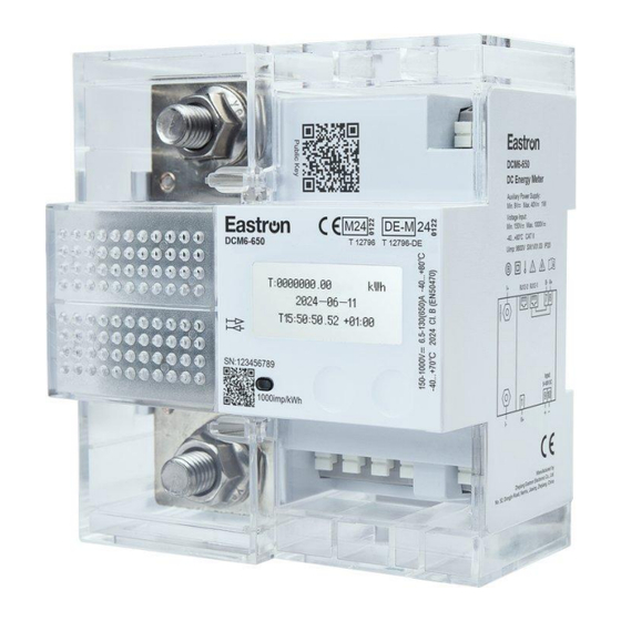
DCM6 Series User Manual V1.2 1. Properties 1.1 Introduction The DCM6-650/DCM6-200 is a DC meter for direct installation in EV charging stations. It provides the measurement data records with timestamp, loading process data and digital signature, thereby enabling charging processes to be billed in accordance with the legal requirements. Furthermore, all charging processes are persistently stored in the internal data storage of the meter. -
Page 6: Specifications
DCM6 Series User Manual V1.2 1.2 Specifications Type DCM6-650 DCM6-200 Voltage 1000 V Umax 150 V Umin Current Starting current Ist 0.52 A (DCM6-650) 0.08A (DCM6-200) 6.5 A (DCM6-650) 1A (DCM6-200) Minimum current Imin 13 A (DCM6-650) 4A (DCM6-200) Current Itr... -
Page 7: Technical Standard
DCM6 Series User Manual V1.2 Table 1: Electrical and mechanical specifications. Temperature Range Typical Operation -40°C to +80°C Storage -40°C to +85°C Humidity max.98%, not condensing EN60068-2-30:1999 Environmental conditions Mechanical environmental conditions Electromagnetic environmental conditions Housing Dimension DIN-Rail 115 mm(L) x 103mm(W) x 64 mm(H) -
Page 8: Additional Documents And Tools
2.3 Disposal (product end of life information) This meter was designed and built by EASTRON to provide many years of service and is backed by our commitment to provide high quality support. When it eventually reaches the end of its serviceable life, it should be disposed of in accordance with local or national legislation. -
Page 9: Service And Warranty
This meter product is warranted against defects in material and workmanship for a period of one year from date of shipment. During the warranty period EASTRON will at its option, either repair or replace products which prove to be defective. For warranty service or repair, this product has to be returned to a service facility designated by EASTRON. -
Page 10: Housing
DCM6 Series User Manual V1.2 Transparency software has to be used to display the invoiced data in compliance with the legal requirements, which enables signature verification of the measurement data records for invoice control. The transparency software is ready for download at: •... -
Page 11: Installation And Safety
DCM6 Series User Manual V1.2 Figure 4 constructional drawing (Dimension in mm) 4.2 Installation and Safety The meter and all associated components may only be installed in compliance with all safety regulations. Ignoring these instructions may endanger life and the manufacturer will not take any responsibility. - Page 12 DCM6 Series User Manual V1.2 two devices can be established via one of the three RJ12 interfaces. After installation of the meter, it is mandatory to change the operating mode from assembling mode to user mode. The manufacturer is not responsible for any damage caused by disregarding this instruction.
-
Page 13: Marking
DCM6 Series User Manual V1.2 Item Description Notes Terminals “+” and “- “on the Current terminals M10 screws Copper Shunt Voltage terminals #1: V+ AWG16-20 #9 (+), #10(-): 9~40V DC DC Power supply terminals Terminal:WJ237/5.0 Communication RJ12- 1/ terminal 7-8: Communication... -
Page 14: Display
DCM6 Series User Manual V1.2 6. Display The LCD is dot matrix type with the format 37.5 mm × 17 mm. Figure 8: Schematic of the Dot Matrix LC Display (unit: mm) 6.1 Internal Display State Machine The control of the internal display consists of a state machine which changes the current display state according to the present meter data.Figure 9 shows the complete display state machine with all transitions... -
Page 15: Display Description
DCM6 Series User Manual V1.2 6.2 Display Description 6.2.1 General State In the Display Self-test mode, the meter performs a self-testing on the display to ensure all pixels are fully functional. During this test sequence, the display will shows up all pixels for 3 seconds and turn off all pixels for another 3 seconds. -
Page 16: Available Button Actions
DCM6 Series User Manual V1.2 encryption firmware version 2. SV2:01.01 Measuring chip firmware version 3. CRC1:AE858839 MCU firmware CRC 4. CRC2:994C834B Measuring chip firmware CRC 5. SN:987654321 Series number of the meter 6. CX:0382 Eastron Firmware code *1: this info contains measurement mode code and firmware version and encryption chip’s firmware version. -
Page 17: Display Charging State
DCM6 Series User Manual V1.2 6.2.5 Display Charging State Screen Description 2-wire system (Line 2-wire system (Line loss 4-wire system loss function off ) function on) Energy Kwh display Energy Energy-M Energy-M Energy-L Energy-L D&T Time display Date Date Date... -
Page 18: Normal Display
DCM6 Series User Manual V1.2 The charging summary status displayed is basically a summary of the charging process that was just executed. All instrument values required for the complete billing process should be displayed to the customer. So for DCM6-650/-200 series,during the charging process, there is only one difference between the normal display interface and the uncharged interface. -
Page 19: Public Key Display
DCM6 Series User Manual V1.2 Configure historical data: In the electricity history data interface, short press the ENTER button to enter the configuration history data screen. Configure historical data to query up to 99 entries. First line: Configuration data page number Second line: The time when the historical data occurred. -
Page 20: User Buttons
DCM6 Series User Manual V1.2 visible. Assembling mode symbol. Figure below the symbol, which indicates a currently active assembling mode of the meter. This mode is only available during assembly of the charging point. The symbol remains visible as long as the assembling mode is active. -
Page 21: Communication
MODBUS Protocol functions used by the Eastron Digital meters copy 16 bit register values between master and slaves. However, the data used by the Eastron Digital meter is in 32 bit IEEE 754 floating point format. Thus each instrument parameter is conceptually held in two adjacent MODBUS Protocol registers. Query The following example illustrates a request for a single floating point parameter i.e. - Page 22 DCM6 Series User Manual V1.2 Error Check (Hi): The top (most significant) eight bits of a 16-bit number representing the error check value. Response The example illustrates the normal response to a request for a single floating point parameter i.e. two 16-bit Modbus Protocol Registers.
-
Page 23: Input Register
DCM6 Series User Manual V1.2 No. of registers =0002 Amps 2 Start address=0008 No. of registers=0002 Each request for data must be restricted to 40 parameters or less. Exceeding the 40 parameter limit will cause a Modbus Protocol exception code to be returned. - Page 24 DCM6 Series User Manual V1.2 320017 Negative charging gun energy Float...
- Page 25 DCM6 Series User Manual V1.2 Integer register 310001 Total import active energy . Int64 310005 Total export active energy . Int64 310021 Total active Energy Int64 310251 Volts Int32 0.1V 310257 Current Int32 0.001A 310263 power Int32 0.1W 310309 Line Loss power Int32 0.1W...
-
Page 26: Holding Registers
DCM6 Series User Manual V1.2 320269 Total Charging gun energy Int64 Holding Registers Holding registers are used to store and display instrument configuration settings. All holding registers not listed in the table below should be considered as reserved for manufacturer use and no attempt should be made to modify their values. - Page 27 DCM6 Series User Manual V1.2 Write the network port baud rate for MODBUS Protocol, where: 0 = 2400 baud. 1 = 4800 baud. Network Baud 40029 2 = 9600 baud, default. Rate 3 = 19200 baud. 4 = 38400 baud...
- Page 28 DCM6 Series User Manual V1.2 Data Format :Hex Charging history data length The length of 1~1024 401543 charging data Length : 2byte Data Format :Hex Retrieved Length :1024byte 401545 charging data Data Format :ASCII Total number of logs Total log data...
- Page 29 DCM6 Series User Manual V1.2 status 0x01:Idle 0x02:Signature in progress 0x03:Signature OK 0x04:Invalid date time 0x05:Invalid measurement 0x06: signature state error 0x07:Keypair generation Error 0x08:SHA failed 0x09:Public key error 0x10:Invalid message format 0x11:Invalid message size 0x12:Signature error 0x13:Undefined error Length:2 bytes...
- Page 30 DCM6 Series User Manual V1.2 4 = 38400 baud 6 = 115200baud Data Format:float(length:4 byte) time zone Range: -12~12 461439 Zone Length: 4 bytes Data Format: float s-min-hour-week-Date-Month-Year-20 461441 Time Length : 8 byte Data Format:BCD Day-hour-minute, day = 2byte;...
-
Page 31: Ocmf Holding Registers
DCM6 Series User Manual V1.2 Note: Only read Meter code 8000 Length : 2 byte 464515 Meter code Data Format : hex Note: Only read The version number of the LCD display of the electricity meter is XX.YY The version... - Page 32 DCM6 Series User Manual V1.2 BIT14:PLMN_NONE BIT15:PLMN_RING BIT16:PLMN_SMS Length : 4 byte Data Format : HEX Note: Up to 4, rewrite overwrite, will not clear Type of identification data 0x0000:NONE 0x0001:DENIED 0x0002:UNDEFINED 0x0003:ISO14443 0x0004:ISO15693 0x0005:EMAID 0x0006:EVCCID 0x0007:EVCOID 0x0008:ISO7812 0x0009:CARD_TXN_NR 46149...
-
Page 33: Private / Public Key Read
DCM6 Series User Manual V1.2 Available in administrator mode Data Format :ASCII Note: Rewriting will overwrite and not clear TarifText Length : 10byte 46177 Data Format :ASCII Note: It needs to be rewritten before each charging. Not covering will display the last charging data. - Page 34 DCM6 Series User Manual V1.2 The meter readings that are written to the OCMF load log are similar to the values displayed on the meter display. They depend on the configuration settings. Note: All Energy Values of the following chapters are parsed into the OCMF file with 3 decimal counts.
-
Page 35: System Architecture
DCM6 Series User Manual V1.2 "SD":"3046022100bb1e83b32a0792dbaa8db595d8743f6db4288771dd6096177db4a62a94575aaf022100a 429e6cd787060844ed3ab6c1ec718b7890e25f150fee5ecdcd8ef6d57419479" 9. System Architecture 9.1 System Overview The meter consists of two independent components: A metering part and an application part. Both parts communicate via a non-reactive serial interface. Simplified block diagram of the DCM6-650/-200 9.2 Measurement... -
Page 36: Functional Description
DCM6 Series User Manual V1.2 10. Functional Description 10.1 About Line Loss The DCM6-650/-200 can calculate the line loss energy. For that reason, the impedance (Rline) has to be configured. The impedance can only be changed in assembling mode. A change of the impedance is recorded in the logbook. - Page 37 DCM6 Series User Manual V1.2 For Import Energy Mode the register values for every point in time are given by: Total Import Mains Energy = Total Import Device Energy + Total Import Line Loss Energy , with Rline = (Rline1 + Rline2 ) > 0, which is illustrated inFigure 28.
-
Page 38: Eastron Ev-Meter Dc Test
11. EASTRON EV-METER DC TEST 11.1 Introduction: “EASTRON EV-METER DC TEST” is a software that simulates the operation of charging piles. The software can perform charge and discharge, signature verification and historical data reading functions. And with a debugging interface, you can view the communication data, which helps customers quickly develop management software. -
Page 39: Operation
DCM6-650 User Manual V1.2 1) The computer must support the .NET Framework 3.8 2) The minimum system version supports Windows 7 Service Pack 1 11.4 Operation 11.4.1 Communication connection Screen : 1. Communication port 2. Baud rate 3. Data bits 4. -
Page 40: Parameter Settings
DCM6-650 User Manual V1.2 Choose right communication parameter. (default : 19200,8,none,1),click the button “Connect”. when the SN pop up, it means the connection succeed. 11.4.2 Parameter Settings 1. Com 1 network parity stop 2. Com 2 network parity stop 3. Network Node: Modbus address 4. -
Page 41: Connect Mode
DCM6-650 User Manual V1.2 9. Set Assembling Mode: change the meter into Assembly Mode by enter the password. 10. Set User Mode: change the meter into user mode by enter the password. 11. Set CT, CI 12. Format version: to read OCMF version 13. -
Page 42: Measurement
DCM6-650 User Manual V1.2 11.4.3 Measurement When the meter is connected to the load, we can already read the measurement data through the meter, click the Refresh Measurements button, and refresh the measurement parameters. 11.4.4 Charge 1. OCMF display. 2. IS settings. 3. - Page 43 DCM6-650 User Manual V1.2 6. Start charging. 7. End charging. 8. Charging status display. 9. Verify OCMF data 10. Export public key address selection. 11. Export signature data address selection. 12. Export public key data. 13. Export signature data. 14. Public key display window. 15.
-
Page 44: History
DCM6-650 User Manual V1.2 11.5 History 1. Read historical charging data labels. 2. Read historical configuration data labels. 3. Choose between reading all and reading a single ID. 4. Query 5. Stop 6. Data display window Click the query button to query the historical charging data. - Page 45 DCM6-650 User Manual V1.2 If you have any question, please feel free to contact our sales team. EASTRON ELECTRONIC CO., LTD. No. 52, Dongjin Road, Nanhu, Jiaxing, Zhejiang, China Tel: +86-573-83698881 Fax: +86-573-83698883 Email: Sales@eastrongroup.com www.eastrongroup.com...
Need help?
Do you have a question about the DCM6 Series and is the answer not in the manual?
Questions and answers