Table of Contents
Advertisement
Quick Links
Technical Support and E-Warranty Certificate www.vevor.com/support
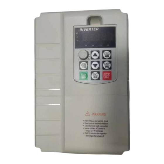
Inverter
MODEL:AT1-7500X
We continue to be committed to provide you tools with competitive price.
"Save Half", "Half Price" or any other similar expressions used by us only represents an
estimate of savings you might benefit from buying certain tools with us compared to the major
top brands and does not necessarily mean to cover all categories of tools offered by us. You
are kindly reminded to verify carefully when you are placing an order with us if you are
actually saving half in comparison with the top major brands.
Advertisement
Table of Contents

Related Manuals for VEVOR AT1-7500X


Summary of Contents for VEVOR AT1-7500X
- Page 1 Technical Support and E-Warranty Certificate www.vevor.com/support Inverter MODEL:AT1-7500X We continue to be committed to provide you tools with competitive price. "Save Half", "Half Price" or any other similar expressions used by us only represents an estimate of savings you might benefit from buying certain tools with us compared to the major top brands and does not necessarily mean to cover all categories of tools offered by us.
- Page 2 This is the original instruction, please read all manual instructions carefully before operating. VEVOR reserves a clear interpretation of our user manual. The appearance of the product shall be subject to the product you received. Please forgive us that we won't inform you again if there are any technology or software updates on our product.
-
Page 3: Important Safeguards
IMPORTANT SAFEGUARDS Read all safety warnings, instructions, illustrations and specifications provided with this inverter. Failure to follow all instructions listed below may result in electric shock, fire and/or serious injury. WARNING : This equipment is a high voltage device, please do not attempt to disassemble this equipment at any time to avoid danger. -
Page 4: Fcc Information
FCC Information CAUTION: Changes or modifications not expressly approved by the party responsible for compliance could void the user's authority to operate the equipment! This device complies with Part 15 of the FCC Rules. Operation is subject to the following two conditions: 1) This product may cause harmful interference. -
Page 5: Correct Disposal
Correct Disposal This product is subject to the provision of European Directive 2012/19/EC. The symbol showing a wheelie bin crossed through indicates that the product requires separate refuse collection in the European Union. This applies to the product and all accessories marked with this symbol. Products marked as such may not be discarded with normal domestic waste, but must be taken to a collection point for recycling electrical and electronic device 1. - Page 6 Project Standard V/F control Type-G Mode: 0.3Hz/150% (SVC). Starting torque Type-P Mode: 0.3Hz/100% Range of ADJ 1:100(SVC) Speed Stable speed ±0.5%(SVC) accuracy Type G:150% Rated Current 120s;180% for Overload capacity Type P:120% Rated Current for 60s;150% for Automatic torque increase; Torque rise Manual torque increase: 0.1% -30.0% Three ways: straight line;...
- Page 7 Project Standard Panel potentiometer, Number given,External Frequency analog voltage/current input, and serial port source input.can be switched in multiple ways Five digital input terminals Input Terminal 1 analog quantity input terminal; One 0-10V voltage or 0-20mA current input; 1 digital output terminal Output 1 relay output terminal(TA,TB,TC) Terminal...
- Page 8 Figure 1-3-1 0.75-11.0KW wiring diagram control terminal description - 7 -...
-
Page 9: Operation And Display
2. Operation and display Function indicator lamp description ◈ Hz:Frequency display indicator lamp ◈ V: Voltage indicator lamp ◈ A: Current indicator lamp ◈ ERR: fault indicator lamp ◈ F / R: Forward and Reverse indicator lamp ◈ L / R: Communication control indicator lamp ◈... - Page 10 3. Summary table of functional parameters: P00, Monitoring group P00.00 running frequency 0.00 ~ 320.00Hz(P01.22=2) - P00.01 Set the Frequency 0.0 ~ 3200.0Hz(P01.22=1) - P00.02 Busbar voltage (V) 0.0V ~ 3000.0V 0V ~ 1140V P00.03 Output voltage (V) P00.04 Output Current (A) 0.00A ~...
- Page 11 P00.30 Frequency X Display 0.00Hz ~ 500.00Hz P00.31 Frequency Y Display 0.00Hz ~ 500.00Hz P00.32 View any memory address value 0 ~ 65535 P00.35 Target torque, (%) 0.0°~ 359.9° P00.37 Power factor Angle P00.39 Target voltage of VF separating 0V ~ Motor rated voltage P00.40 Output voltage of VF separating 0V ~ Motor rated voltage...
- Page 12 channel 1: Terminal Run channel ("L/R" lights on) 2: Communication command channel ("L/R" lights flashing) 0: Digital set (preset frequency P01.08, keypad ▲/▼ key,power loss) 1: Digital set (preset frequency P01.08, keypad ▲/▼ key,Power drop memory) 2: AI1 analog set (0-10V); Main frequency P01.03 3: AI2 analog set(0-10V or...
- Page 13 results (operation relationship is determined by Ten digits) 2: Main frequency X and Secondary frequency Y switch 3: Switch between main frequency X and Main and Secondary operation results 4: The frequency Y switches with Main and Secondary operation results Ten digits: Frequency operation relationship of X and Y 0: X +Y...
- Page 14 Lower limit P01.14 0.00Hz ~【P01.12】 0.00Hz ☆ frequency P01.15 Carrier frequency 0.5kHz ~ 16.0kHz For Model ☆ Carrier frequency P01.16 Adjust with 0: No,1: Yes ☆ temperature Acceleration time 0.00s ~ 650.00s(P01.19=2) P01.17 ☆ 0.0s ~ 6500.0s(P01.19=1) For Model 0s ~ 65000s(P01.19=0) Deceleration time P01.18 ☆...
- Page 15 benchmark Single digit: Operation Panel command binding frequency source selection 0: No binding 1: Digital set 2:AI1 3:AI2 4:AI3 5: Pulse set (0~50KHZ DI5); 6: Multi segment speed; 7: Simple PLC Command source 8:PID P01.27 bundled 9: Communication Set 0000 ☆...
- Page 16 Rated frequency 0.01Hz~ Maximum output P02.04 ★ of motor frequency【P01.10】 Rated speed of P02.05 1rpm ~ 65535rpm ★ motor 0.001Ω ~ 65.535Ω (Inverter Stator resistance power <=55kW) P02.06 ★ of motor 0.0001Ω ~ 6.5535Ω (Inverter power> 55kW) 0.001Ω ~ 65.535Ω (Inverter Rotor resistance power <=55kW) P02.07...
- Page 17 Speed loop P03.01 0.01s ~ 10.00s 0.50s ☆ integration time 1 Switch frequency P03.02 0.00 ~ 【P03.05】 5.00Hz ☆ Speed loop P03.03 1 ~ 100 ☆ proportional 2 Speed loop P03.04 0.01s ~ 10.00s 1.00s ☆ integration time 2 Switch frequency P03.02 ~Maximum output P03.05 10.00Hz...
- Page 18 torque regulation Integral gain of P03.16 0 ~ 60000 1300 ☆ torque regulation P04 V/F Control Parameters 0: linear curve V/ F 1: Multipoint curve V/ F 2: Decreasing torque curve 1 (Square curve) 3: Decreasing torque curve 2 (1.2 power) 4: Decreasing torque curve 2 P04.00 VF curve setting...
- Page 19 Multi-point V/F 【P04.05】~ Motor Rated P04.07 0.00Hz ★ Freq. 3 frequency 【P02.04】 Multi-point V/F P04.08 0.0% ~ 100.0% 0.0% ★ Voltage 3 V/F control Slip 0.0% ~ 200.0% P04.09 frequency 0.0% ☆ compensation V/F Over P04.10 0 ~ 200 ☆ excitation gain Oscillation P04.11...
- Page 20 Over-current stall P04.18 50% ~ 200% 150% ★ action current Suppression of 0: Disable, P04.19 ★ Over current stall 1: Enable. Suppression’s 0 ~ 100 P04.20 gain of Over ☆ current stall Compensation coefficient of P04.21 50% ~ 200% ★ action Over current stall Over-voltage stall...
- Page 21 6: Freq. Increase(Terminal UP) 7: Freq. decrease(Terminal DOWN) 8: Free shutdown control 9: External reset signal input(RST) 10: Suspend operation; 11: External fault normally-open (NO) input 12: Multi-speed 1 13: Multi-speed 2 14: Multi-speed 3 15: Multi-speed 4 16: ACC/DEC time select 1( TT1) 17: ACC/DEC time select 2( TT2) 18: Frequency source switch 19: UP/DOWN Freq.
- Page 22 closed,NC) 34: Frequency modification Enables 35: PID input signal reversed; 36: External parking terminal 1 37: Run command Switch terminal 2 38: PID integral Pause; 39: Frequency X switches with the Preset frequency 40: Frequency Y switches with the Preset frequency 41: Motor selection terminal 1 43: The PID Parameters switch 44: User defined fault 1...
- Page 23 setting Pulse function, P05.04=30) P05.10 DI filtering time 0.000s ~ 1.000s 0.010s ☆ 0: Two-wire control mode 1, Terminal control 1: Two-wire control mode 2, P05.11 ★ Mode 2: Three-wire control mode 1, 3: Three-wire control mode 2. Frequency P05.12 adjusting step 0.001Hz/s ~...
- Page 24 AI curve 2 filtering P05.22 0.00s ~ 10.00s 0.10s ☆ time AI curve 3's Min. P05.23 -10.00V ~ P05.25 -10.00V ☆ input Corresponding -100.0% ~ +100.0% P05.24 value of AI curve 0.0% ☆ 3's Min. input Max. input of AI P05.25 P05.23 ~...
- Page 25 4: AI curve 4 (4 PM, see P24.00~P24.07) 5: AI curve 4 (4 PM, see P24.08~P24.15) Ten bit: AI2 curve selection (the same as Single bit 1~5) Hundred bit: AI3 curve selection (the same as above) Single bit: AI1 below Min. input setting 0: Corresponding value of Min.
- Page 26 Ten Bit: DI7 P06 group, Output Parameters DO1 output 0: No output P06.01 ☆ function selection 1: Running indicator; 2: Fault output (for free shutdown fault) 3: Freq. level detection signal 1(P14T1) 4: Frequency arrival indicator(FAR) 5: VFD zero-speed running(When running) 6: Motor overload Early-warning 7: Inverter overload Early-warning...
- Page 27 22: Location proximity (reserved) 23: Zero-speed running 2 (also output when shutdown) 24: Accumulated power-on time arrives 25: Freq. level detection signal 2(P14T2) 26: Output freq. 1 reached 27: Output freq. 2 reached 28: Output Current 1 reached 29: Output Current 2 reached 30: Regularly reached 31: Input signal Al1 overrun 32: Load dropping...
- Page 28 6: Input pulse freq. 7:AI1 8:AI2 9:AI3 10: Length 11: Count value 12: Communication setting, 13: Motor speed 14: Output Current. (100.0% Corresponding to 1000.0A) 15: Output voltage (100.0% Corresponding to 1000.0V) 16: Motor output torque (Percentage of actual value relative to motor rating) 17: VFD output torque (Percentage of actual value...
- Page 29 Hundred Bit: RELAY2 P07 group, Start and Stop control Parameters 0: Direct start 1: Start with speed tracking P07.00 Starting mode ☆ 2: DC braking + start at start frequency 0: Start with the shutdown frequency Speed tracking 1: Start with the working P07.01 ★...
- Page 30 0: Decelerate to stop 1: Coast to P07.10 Stop mode ☆ stop Frequency 0.00Hz ~ Maximum freq. P07.11 threshold of DC 0.00Hz ☆ 【P01.10】 brake DC brake delay P07.12 0.0s ~ 100.0s 0.0s ☆ time P07.13 DC brake current 0% ~ 100% ☆...
- Page 31 Bit03: Output Voltage (V) Bit04: Output current (A) Bit05: Output power (kW) Bit06: Output torque (%) Bit07: DI input status Bit08: DO output status Bit09: AI1 voltage (V) Bit10: AI2 voltage (V) Bit11: AI3 voltage (V) Bit12: Count value Bit13: Length value Bit14: Load speed display Bit15: PID settings 0000 ~...
- Page 32 Bit13: Encoder feedback speed (Hz) Bit14: Main Frequency X Display (Hz) Bit15: Secondary frequency Y Display (Hz) 0000 ~ FFFF Bit00: Set Frequency (Hz) Bit01: Bus Voltage (V) Bit02: DI input status Bit03: DO output status Bit04: AI1 voltage (V) LED displays Bit05: AI2 voltage (V) P08.05...
- Page 33 Recommended time: P09.02 Jog Dec time 20.0s ☆ 0.4 ~ 4.0KW 7.5S Acceleration time 5.5 ~ 30.0KW 15.0S P09.03 ☆ 37.0 ~ 132.0KW 40.0S Deceleration time 160.0~ 630.0KW 60.0S P09.04 ☆ Acceleration time P09.05 ☆ 15.0 Deceleration time P09.06 ☆ Acceleration time P09.07 ☆...
- Page 34 Setting P09.17 0h ~ 65000h ☆ cumulative running arrival 0: Unprotected; P09.18 Start protection ☆ Frequency 0.00Hz ~ Maximum freq. 50.00 P09.19 detection value 1 ☆ 【P01.10】 (P14T1) Frequency P09.20 detection lag 0.0% ~ 100.0% (P14T1 level) 5.0% ☆ value (P14T1) Frequency 0.0% ~ 100.0% (Maximum P09.21...
- Page 35 detection value 1 Arbitrary arrival 0.0% ~ 100.0% (Maximum P09.31 frequency 0.0% ☆ frequency) detected width 1 Arbitrary arrival 50.00 P09.32 frequency 0.00Hz ~ Maximum frequency ☆ detection value 2 Arbitrary arrival 0.0% ~ 100.0% (Maximum P09.33 frequency 0.0% ☆ frequency) detected width 2 0.0% ~...
- Page 36 selection 1: AI1 2: AI2 3: AI3 Analog input range corresponds to the【P09.44】 Timer running P09.44 0.0Min ~ 6500.0Min 0.0Min ☆ time AI1 input voltage P09.45 protection value 0.00V ~ P09.46 3.10V ☆ lower limit AI1 input voltage P09.46 protection value P09.45 ~...
- Page 37 Motor overload 0: Disable, P10.00 ☆ protection 1: Enable Motor overload P10.01 0.20 ~ 10.00 1.00 ☆ protection gain Motor overload P10.02 early-warning 50 ~ 100% ☆ factor Short circuit to 0: Disable, P10.07 ground protection ☆ 1: Enable when power on Brake unit's 650.0V ~...
- Page 38 Second failure 2: Over-current in Acc process P10.15 ● - type 3: Over-current in Dec process 4: Over-current in constant speed 5: Over-voltage in Acc process 6: Over-voltage in Dec process 7: Over-voltage in constant speed 8: Buffer resistance overload 9: Under-voltage 10: VFD overload 11: Motor overload...
- Page 39 43: Motor over-speed Frequency at the P10.17 third (most ● - - recent) failure Current at the P10.18 third (most ● - - recent) fault Bus voltage at the P10.19 third (most ● - - recent) fault Input terminal status at the third P10.20 ●...
- Page 40 Bus voltage at the P10.29 ● - - second fault Input terminal P10.30 status for the ● - - second failure Output terminal P10.31 status at the ● - - second failure The Inverter P10.32 status at the ● - -...
- Page 41 first failure Single Bit: Motor overload (Err11) Ten Bit: Input phase loss, (Err12) Hundred Bit: Output phase loss, (Err13) Thousand Bit: External fault Fault protection (Err15) P10.47 action 00000 ☆ Ten thousand Bit: selection 1 Communication exception, (Err16) 0: Coast to stop; 1: Stop by Stop mode【P07.10】...
- Page 42 load recovery Ten thousand Bit: PID feedback loss (Err31) 0: Coast to stop; 1: Stop by Stop mode【P07.10】 2: Keep running; Single Bit: Speed deviation too large (Err42) Ten Bit: Motor over-speed (Err43) Fault protection Hundred Bit: (Reserved) P10.50 00000 ☆...
- Page 43 non-stop The judgment 60.0% ~ 100.0% (Standard bus P10.62 voltage of Instant 80.0% ☆ voltage) power non-stop Gain of Instant P10.71 0 ~ 100 ☆ power non-stop Integral coefficient of P10.72 0 ~ 100 ☆ Instant power non-stop Deceleration time P10.73 of Instant power 0 ~...
- Page 44 P11 group PID function 0: P11.01 setting 1:AI1 2:AI2 3:AI3 P11.00 PID input channel ☆ 4: Pulse Setting (DI5) 5: Communication Setting 6: Multistage speed 7: Keyboard encoder settings Digital reference P11.01 0.0~ 10.00 3.00 ☆ input setting 0:AI1 1: AI2 2:...
- Page 45 Differential limiter P11.10 0.00% ~ 100.00% 0.10% ☆ of PID PID Input signal P11.11 0.00 ~ 650.00s 0.00s ☆ change time PID feedback P11.12 0.00 ~ 60.00s 0.00s ☆ filtering time The PID output P11.13 0.00 ~ 60.00s 0.00s ☆ filtering time Proportional gain P11.15...
- Page 46 Max deviation P11.24 deviation of Two 0.00% ~ 100.00% 1.00% ☆ output Single Bit: Integral separation 0: Invalid, 1: valid The PID integral Ten Bit: when the frequency P11.25 ☆ property reaches the limits 0: Continue integral regulation, 1: Stop integral regulation PID feedback 0.1% ~ 100.0% (0.0%:...
- Page 47 P12.05 Setting length 0m ~ 65535m 1000m ☆ P12.06 Actual length 0m ~ 65535m ☆ Number of pulses P12.07 0.1 ~ 6553.5 100.0 ☆ per Meter Setting Count P12.08 1 ~ 65535 1000 ☆ value Specifies Count P12.09 1 ~ 65535 1000 ☆...
- Page 48 Multistage speed P13.11 0.0% ☆ 11 (MS11) Multistage speed P13.12 0.0% ☆ 12 (MS12) Multistage speed P13.13 0.0% ☆ 13 (MS13) Multistage speed P13.14 0.0% ☆ 14 (MS14) Multistage speed P13.15 0.0% ☆ 15 (MS15) 0: End of single operation Simple PLC 1: Final value at end of single P13.16...
- Page 49 MS 3 Multistage speed P13.26 0.0s(h) ~ 6553.5s(h) 0.0s (h) ☆ 4 runtime Acc/Dec time of P13.27 0 ~ 3 ☆ MS 4 Multistage speed P13.28 0.0s(h) ~ 6553.5s(h) 0.0s (h) ☆ 5 runtime Acc/Dec time of P13.29 0 ~ 3 ☆...
- Page 50 Multistage speed P13.42 0.0s(h) ~ 6553.5s(h) 0.0s (h) ☆ 12 runtime Acc/Dec time of P13.43 0 ~ 3 ☆ MS 12 Multistage speed P13.44 0.0s(h) ~ 6553.5s(h) 0.0s (h) ☆ 3 runtime Acc/Dec time of P13.45 0 ~ 3 ☆ MS 3 Multistage speed P13.46...
- Page 51 8:57600BPS 9:115200BPS 0: No check (8.N-2) MODBUS Data 1: Parity check (8.E-1) P14.01 ☆ format 2: Odd check (8.O-1) 3: No check (8.N-1) 0:broadcast address P14.02 Local address ☆ 1~247:(MODBUS) MODBUS P14.03 0 ~ 20ms ☆ Response delay Timeout time of 0.0: Invalid P14.04 ☆...
- Page 52 P15.04 Sleep delay time 0.0s~6500.0s 60.0s ☆ Pressure 0: Disable; P15.05 proportional ☆ 1: Enable linkage Wake-up P15.06 pressure 0~100.0Bar(Kg,0.1Mpa) 0.50KG ☆ difference Sleep pressure P15.07 0~100.0Bar(Kg) 0.50KG ☆ difference Over-pressure 0.00~Pressure Gauge Range P15.08 9.00KG ☆ alarm value KG(1KG=0.1Mpa=1Bar) Delay Time of P15.09 Over-pressure...
- Page 53 turns on Waiting time for P15.16 the auxiliary 0~1000.0S 5.0S ☆ pump switch 0~50HZ RO1 Relay ON P15.17 When reaches the value, the 50.00 ☆ frequency setting Relay will ON 0~50HZ RO1 Relay OFF P15.18 When reaches the value, the 30.00 ☆...
- Page 54 Judgment value 0.0% : Invalid function. for Hydraulic 0.1~100.0%: when Water level P15.23 probe controller signal is greater than 0.0% ☆ damage(Water the【P15.23】 , show (E.tSF) level controller) fault and shut down Water shortage 0: Disable; P15.24 protection 1: Enable, and judge by ☆...
- Page 55 Water leakage 0~Pressure Gauge Range KG P15.31 and then start the ☆ (Bar/0.1Mpa) return value Water leakage and then start the 0: NO Function P15.32 2.0S ☆ return value 0.1.10.0S detection time 0: Disable 1: Sleep when pressure is greater than sleep pressure; 2: Sleep when running frequency is less than sleep frequency Sleep mode...
- Page 56 0: Digital Settings 1: (P18.03) 1:AI1 Torque setting 2:AI2 source selection P18.01 3: AI3 ★ under torque 4: PLUSE Setting control mode 5: Communication setting 6: MIN (AI1, AI2) 7: MAX (AI1, AI2) Digital Setting P18.03 under the torque -200.0% ~ 200.0% (P18.01=0) 150.0% ☆...
- Page 57 Under-voltage P23.06 200.0V ~ 2200.0V 350V ☆ value Setting Over-pressure P23.09 200.0V ~ 2200.0V 270V ★ Value setting Automatic carrier 0: Disable, P23.10 freq change at ☆ 1: Enable low frequency Zero-speed 0: Disable, P23.11 running output ☆ 1: Enable control Sensitivity of P23.12...
- Page 58 Corresponding P24.07 -100.0%~+100.0% 100.0% ☆ ratio of P24.06 Min input of the AI P24.08 -10.00V~P24.10 -10.00V ☆ curve 5 Corresponding P24.09 -100.0%~+100.0% -100.0% ☆ ratio of P24.08 Turning 1 of the AI P24.08~P24.12 P24.10 -3.00V ☆ curve 5 Corresponding P24.11 -100.0%~100.0% -30.0% ☆...
- Page 59 Jump point of -100.0%~100.0% P24.28 0.0% ☆ the Al3 Jump range of P24.29 0.0%~100.0% 0.5% ☆ the Al3 P30 group Correction for the AI and AO AI1 Measured Factory P30.00 0.500V~4.000V ☆ voltage 1 correction AI1 display Factory P30.01 0.500V~4.000V ☆...
-
Page 60: Fault Alarm And Countermeasures
AI3 display Factory -9.999V~10.000V P30.11 ☆ voltage 2 correction AO1 target Factory P30.12 0.500V~4.000V ☆ voltage 1 correction Factory P30.13 0.500V~4.000V ☆ Measured correction voltage 1 AO1 target Factory P30.14 6.000V~9.999V ☆ voltage 2 correction Factory P30.15 6.000V~9.999V ☆ Measured correction voltage 2 AO2 target... - Page 61 fault The input voltage is Check the input power abnormal supply Over voltage Err31 during acceleration Restart when the motor Set to start after DC rotates braking The deceleration time is Extend the deceleration too short time Over voltage Err32 during deceleration The input voltage is...
- Page 62 The Inverter power is too Select Inverter with high small power level Adjust the V / F curve or Improper setting of V/F the torque boost curve or torque. amount The deceleration time is Extend the deceleration too short time OverCurrent Err62 during...
- Page 63 Wave by Same with motor Same with motor Err65 wave current Overload Overload limiting fault restart can not resume hardware Err40 Water, insects, etc back to the factory malfunction repair EEPROM Seek a service from the Err41 EEPROM hitch R/W failure manufacturer The input power supply is Adjust the voltage to the...
- Page 64 Disconnect the External Contact / relay External equipment input fault terminal and clear Err17 failure terminal fault the fault (pay attention to check the cause) Bad cooling fan or Check the Fan or heat Power module Err08 overheated ambient dissipation or wait for overheated temperature cool to try again...
-
Page 65: Setup Description
The motor parameters Set the motor are not set according to parameters according to Motor tuning Err99 the nameplate or the the nameplate and fault motor line is in poor check the lead from the contact Inverter to the motor Water ErrH1 Water shortage failure... - Page 66 Technical Support and E-Warranty Certificate www.vevor.com/support...
Need help?
Do you have a question about the AT1-7500X and is the answer not in the manual?
Questions and answers
Saludos, no puedo cambiar la frecuencia al variador de 50 a 60 hz
To change the frequency from 50Hz to 60Hz on the VEVOR AT1-7500X inverter, adjust the frequency setting parameters. Specifically, set the desired frequency value (e.g., 60.00) in the relevant parameter controlling the output frequency. The exact parameter number is not specified in the context, but it typically involves the main frequency setting or run frequency parameter. Ensure the maximum frequency setting allows 60Hz operation.
This answer is automatically generated
Mi variador no puedo poner la frecuencia en 60 hz
You can't set the frequency to 60 Hz on the VEVOR AT1-7500X inverter because its maximum frequency setting is limited to 50 Hz, as indicated by parameters P15.17 and P15.18, which allow settings from 0 to 50 Hz.
This answer is automatically generated
The VFD does not display forwared or reverse. My motor is running reverse. How to change to forward without changing wires.
To change the direction of the VEVOR AT1-7500X VFD to forward without changing wires, adjust the operation command settings. Specifically, set the run command to "Forward" using the operation panel or control inputs. Ensure the correct parameter (e.g., P01.02 Operation Command) is configured for the desired forward direction.
This answer is automatically generated
Hi, I have a 10 HP motor 60Hz, 1760 RPM, 3 phase. After trying to program this what I got. P08.08 it read 930 P10.15 and P10.16 had Err 33 P10.19 had 327.1 P10.20 had 992 P10.23 had 4789 P10.29 had 328.8 P10.30 had 992 P10.33 had 4786 P10.39 had 328.8 P10.40 had 992 P10.43 had 4786 P11.00 showed 7 put in 0 P11.05 showed 10 put in 20.0 How do I correct Err 33