Page 1
Technical Support and E-Warranty Certificate www.vevor.com/support
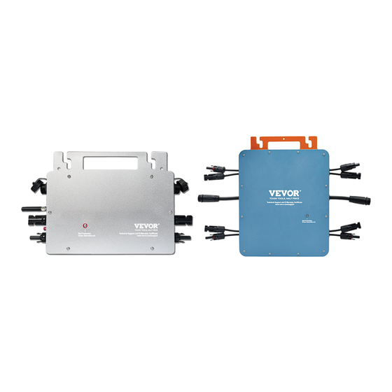
 MICRO INVERTER MODEL:GT-600/GT-800/GT-1200 We continue to be committed to provide you tools with competitive price. "Save Half", "Half Price" or any other similar expressions used by us only represents an estimate of savings you might benefit from buying certain tools with us compared to the major top brands and does not necessarily mean to cover all categories of tools offered by us.
This is the original instruction, please read all manual instructions carefully before operating. VEVOR reserves a clear interpretation of our user manual. The appearance of the product shall be subject to the product you received. Please forgive us that we won't inform you again if there are any technology or software updates on our product.
Warning-To reduce the risk of injury, user must read instructions manual carefully. This product is subject to the provision of European Directive 2012/19/EC. The symbol showing a wheelie bin crossed through indicates that the product requires separate refuse collection in the European Union. This applies to the product and all accessories marked with this symbol.
Page 5
operation and prevented from accidentally being put into operation again; contact qualified maintenance personnel. Ensure that the connection cables are provided with fuses and circuit breakers. Never replace a protective device by a component of a different type. Refer to the manual for the correct part. Check before switching the device on whether the available voltage source conforms to the configuration settings of the product as described in the manual.
SPECIFICATIONS You are welcome to choose our micro grid-connected solar inverter products. Model Specification data GT-600 GT-800 GT-1200 Input Data (DC, PV) Number of Input MC4 Connector 2 sets 4 sets Operation Voltage Range DC18V-50V Maximum input Current 12A*2 14A*2...
INSTALLATION SCHEMATIC Single-phase parallel assembly method of micro inverter GT-600 1. @Single-Phase 230V grid Maximum 4 units 600W Micro inverters per branch. 2. The max DC input power of each inverter is 600W(the PV module max output power is 2x300W).
2. The max DC input power of each inverter is 1200W(the PV module max output power is 2x600W). 3. The VOC of PV modules should not be greater than the max DC input voltage of Micro inverters. WIRING SCHEMATIC Single phase connection method of micro inverter GT-600/GT-800 GT-1200 - 6 -...
Page 9
Three phase connection method of micro inverter GT-600/GT-800 GT-1200 - 7 -...
Page 10
MICRO INVERTER WIFI CLOUD MONITORING 1. Precautions Note that there is a risk of electric shock when connecting the micro-inverter! The micro-inverter heats up during operation! Protect yourself accordingly from burns! Before configuring WiFi cloud monitoring,please correctly install the micro inverter and make it work normally.
Page 11
WIFI Status LED The blue light flashes after always on = the WiFi cloud monitoring module is waiting for configuration. The blue light off after always on = the WiFi cloud monitoring module starts and enters the normal working state. ...
Page 13
6. Usage Of WIFI Cloud Monitoring App. Modify Device Name Click the device to be modified in the device list on the home page to enter the device information details page (Figure 5). - 11 -...
Page 14
Click the button in the upper right to enter the device setting page (Figure 6), Continue to click the upper button to the page of name & position (Figure 7) click name item, then enter a new name and save it (Figure 8).
Page 15
Remove Device Click the device to be deleted in the device list on the home page to enter the device information details page (Figure 5). Click the button in the upper right to enter the device setting page (Figure 6).Click "Remove Device"...
Page 16
Share Device With Others Click the device to be shared in the device list on the home page to enter the device information details page (Figure 5). Click the button in the upper right to enter the device setting page ...
Page 17
INSTRUCTIONS FOR INSTALLATION WIRING 1. The installation process of fixing inverter to PV bracket with mounting screws is as follows: GT-600/800 GT-1200 2. Connect the DC of PV to the inverter, and pay attention to distinguish between positive and negative, as shown below:...
Page 18
4. Repeat steps 1 to 3 to complete the installation of the micro inverter. 5. Connect multiple inverters through AC output cables. 6. The AC main cable is connected to the power grid. AC230V 50Hz AC110V 60Hz SCHEMATIC DIAGRAM OF THE COMPLETION OF THE INSTALLATION - 16 -...
Page 20
GT-1200 Note: When the inverter is purchased for the first time and connected to the mobile phone for monitoring, it is only necessary to switch on the mains AC, the blue light beside it flashes, and the inverter can be connected through WIFI or Bluetooth pairing.
Page 21
1. WHAT TO DO when the Smart-App can't find the micro inverter to be added? Check the following points: Check if the WiFi status indicator of the micro inverter is in the "Blue Flashing" state. Check if the Bluetooth function of your smart device is turned on. ...
Page 22
You can use an idle smartphone to open the WiFi sharing of mobile phone signal hotspot for connection, and reconfigure the network connection after installing the router. 6. There are multiple WiFi signals around. Can we connect different WiFi signals? No, the WiFi connected of the micro inverter and the smart phone must be consistent before the network can be configured.
Need help?
Do you have a question about the GT-600 and is the answer not in the manual?
Questions and answers