Advertisement
Technical Support and E-Warranty Certificate www.vevor.com/support
We continue to be committed to provide you tools with competitive price.
"Save Half", "Half Price" or any other similar expressions used by us only
represents an estimate of savings you might benefit from buying certain tools with
us compared to the major top brands and does not necessarily mean to cover all
categories of tools offered by us. You are kindly reminded to verify carefully when
you are placing an order with us if you are actually saving half in comparison with
Inverter
MODEL: AT1-2200X
the top major brands.
Advertisement
Table of Contents

Related Manuals for VEVOR AT1-2200X


Summary of Contents for VEVOR AT1-2200X
- Page 1 Technical Support and E-Warranty Certificate www.vevor.com/support Inverter MODEL: AT1-2200X We continue to be committed to provide you tools with competitive price. "Save Half", "Half Price" or any other similar expressions used by us only represents an estimate of savings you might benefit from buying certain tools with us compared to the major top brands and does not necessarily mean to cover all categories of tools offered by us.
- Page 2 This is the original instruction, please read all manual instructions carefully before operating. VEVOR reserves a clear interpretation of our user manual. The appearance of the product shall be subject to the product you received. Please forgive us that we won't inform you again if there are any technology or software updates on our product.
- Page 3 IMPORTANT SAFEGUARDS Read all safety warnings, instructions, illustrations and specifications provided with this inverter. Failure to follow all instructions listed below may result in electric shock, fire and/or serious injury. WARNING : This equipment is a high voltage device, please do not attempt to disassemble this equipment at any time to avoid danger.
-
Page 4: Fcc Information
FCC Information CAUTION: Changes or modifications not expressly approved by the party responsible for compliance could void the user's authority to operate the equipment! This device complies with Part 15 of the FCC Rules. Operation is subject to the following two conditions: 1) This product may cause harmful interference. -
Page 5: Correct Disposal
Correct Disposal This product is subject to the provision of European Directive 2012/19/EC. The symbol showing a wheelie bin crossed through indicates that the product requires separate refuse collection in the European Union. This applies to the product and all accessories marked with this symbol. Products marked as such may not be discarded with normal domestic waste, but must be taken to a collection point for recycling electrical and electronic devices. -
Page 6: Terminal Description
2. Terminal description Functional Port Instructions description 15V power output 200mA15V output Input port6 Short Port X6 and COM, input signal (Reversing switch) effective Input port 5(Reverse Short Port X5 and COM, input signal rotation Control switch) effective Input port 4(Forward Short Port X4 and COM, input signal rotation Control switch) effective... - Page 7 3. Multi-speed input Frequency control table : Section Section Section Original speed input 1 speed input 2 speed input 3 Frequency Main Speed Section speed 1 Section speed 2 Section speed 3 Section speed 4 Section speed 5 Section speed 6 Section speed 7 0 means input Port connect with COM, 1 means Note:...
- Page 8 4. Basic operation wiring diagram (1) Single-phase input three-phase output ( Three phase 220V, if 380V Star-connection method needs to change to the 220V Delta-connection method) - 7 -...
-
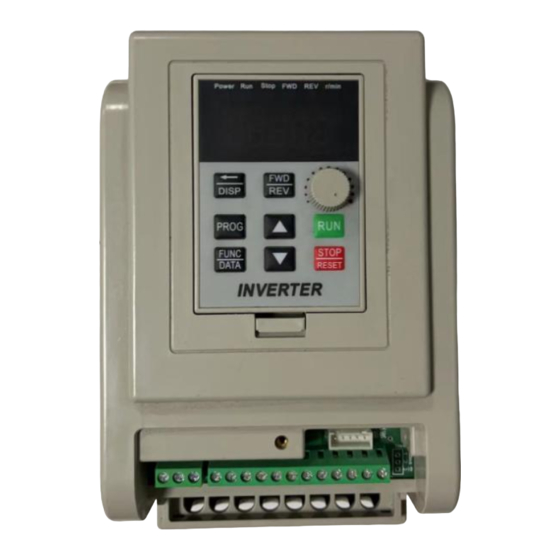
Page 9: Operation Panel
5. Operation panel - 8 -... - Page 10 6. Keys instructions Icon Function description For selecting mode or Programming mode (it is (Programming) available not mater the Inverter star or stop), press this key for modifying parameters. Function data setting key. Normal mode: press this key to display the information of the (Function/ Save) Inverter,such as target frequency, output frequency and current, temperature;...
-
Page 11: Chapter 2 Parameter Specification
Chapter 2 Parameter specification 1. Parameter specification Parameter Parameter Parameter range Default Unit specification Maximum 0---220.0/380.0 220/380 voltage Reference 0---400.0 frequency Intermediate 0---220.0/380.0 110/190 voltage Intermediate 0---400.0 frequency Minimum 0---220.0/380.0 voltage Minimum 0---400.0 frequency Maximum 0---400.0 65.0 operating Minimum 0---400.0 operating Hide password 0---65535... - Page 12 2: Brake stop; 3:Emergency brake. Braking time 0---2.5 Braked Voltage 0---140.0 Machine 1-255 number Operating 0---100.0 arrival Over temperature 1---80 protection selection Revolution 0-8000 2800 50Hz Carrier setting 1---20 Frequency 0.1H adjusting step 1---100 size Overload protection buffer 0.1---60.0 time Working 0---400.0 frequency...
- Page 13 Section speed 5 0---400.0 setting Section speed 6 0---400.0 setting Section speed 7 0---400.0 setting Main rising 1---1000 Hz/S velocity 1st rising 1---1000 Hz/S velocity 2nd rising 1---1000 Hz/S velocity 3rd rising 1---1000 Hz/S velocity 4th rising 1---1000 Hz/S velocity 5th rising 1---1000 Hz/S...
- Page 14 velocity 6th descent 1---1000 Hz/S velocity 7th descent 1---1000 Hz/S velocity Multi function 0:invalid,terminal is input 1 non-functioning (X1 binding 1:wire control stop post) 2:keying stop; 3:keying operation; Multi function 4:stop keying; input 2 5:wire forward operation Multi function 6:wire reverse input 3 operation;...
- Page 15 19: Emergency stop; 20:Relay Control. 0: invalid, no output; 1:operating instructions; Multi function 2:set arrival instructions input 1 (SP1) 3: fault indication; 5: Emergency stop; 6: For P50---P55=20; Multi function Idem (Relay output) input 2 0: setting frequency; 1: operating frequency; Display options 2: revolution 3: current;...
- Page 16 Torque compensation 0---300.0 voltage Torque compensation 0---100 setting Maximum external 31440 analog 0---65535 Minimum external 2096 analog 0---65535 Zero current compensation 0---65535 1130 value Current 0---65535 28000 coefficient 0---65535 Parameter reset (It is the reset when 54321) Main current 0-65535 12000 overload First current...
- Page 17 overload Seventh current 0-65535 12000 overload Jog forward 0---400.0 frequency Jog reverse 0---400.0 frequency Jog rising 1---1000 Hz/S velocity Jog descent 1---1000 Hz/S velocity 0:Inertia stop; Jog stopping 1:Decelerate stop; modes 2:Braking stop; 3:Emergency brake. Jog braking 0---2.5 time Fan start =0 Fan running when P124 ℃...
-
Page 18: Fault Code
3. Parameter setting procedure: 1. Press the programming key to enter into the programming state; 2. Use the arrow keys and shift key to find the parameters that need to be modified; 3. Press function/save key to enter into the parameter; 4. - Page 19 Over voltage protection Err 3 Err 4 Driving Circuit Failures Err 5 Input at startup when electrified Err 6 Over current protection Err 7 Overtime Err 8 Excessive temperatures for radiator Err 9 External fault Made In China - 18 -...
- Page 20 Technical Support and E-Warranty Certificate www.vevor.com/support...
Need help?
Do you have a question about the AT1-2200X and is the answer not in the manual?
Questions and answers
3-wire control wiring and programming on AT1-2200X
To perform 3-wire control wiring and programming on the VEVOR AT1-2200X:
Wiring:
1. Connect a 15V power supply (from the 15V terminal) to the common (COM) terminal.
2. Use three input ports for the 3-wire control:
- X1: Wire control stop (P50 = 1)
- X2: Wire forward operation (P51 = 5)
- X3: Wire reverse operation (P52 = 6)
Programming:
1. Set parameter P50 to 1 for X1 to act as wire control stop.
2. Set parameter P51 to 5 for X2 to act as forward run.
3. Set parameter P52 to 6 for X3 to act as reverse run.
This setup allows start, stop, and direction control using external switches.
This answer is automatically generated
Come si salva un parametro modificato? Grazie
To save a modified parameter on the VEVOR AT1-2200X inverter:
1. Press the programming key to enter the programming state.
2. Use the arrow keys and shift key to find the parameter to modify.
3. Press the function/save key to enter the parameter.
4. Use the arrow keys and shift key to change the parameter value.
5. Press the function/save key to store the parameter.
6. Press the programming key to exit the programming state.
This answer is automatically generated
Program nem módositható .Csak a P09