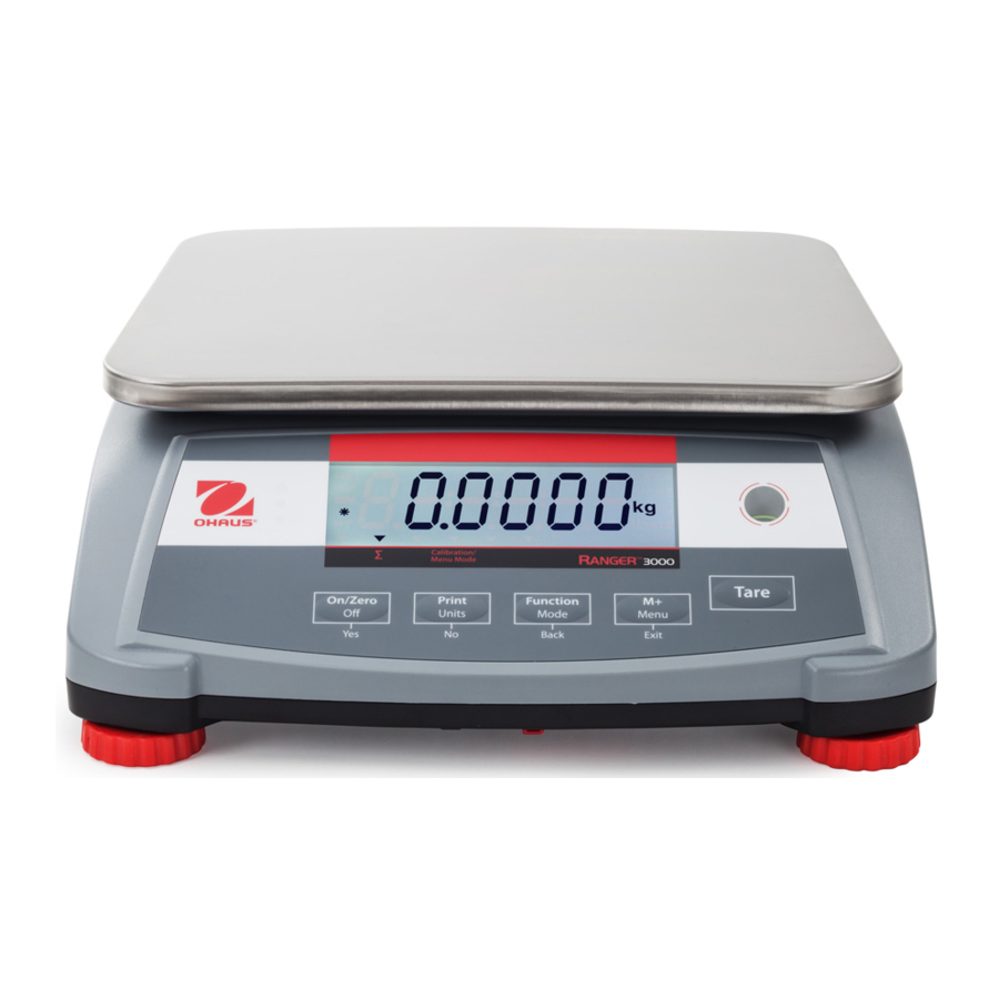
OHAUS Ranger 3000 Series Manual
- Instruction manual (240 pages) ,
- User manual (57 pages) ,
- Service manual (44 pages)
Advertisement
INTRODUCTION
This manual contains installation, operation and maintenance instructions for the Ranger™ 3000 Series. Please read the manual completely before using the scale.
Definition of Signal Warnings and Symbols
Safety notes are marked with signal words and warning symbols. These show safety issues and warnings. Ignoring the safety notes may lead to personal injury, damage to the instrument, malfunctions and false results.
Signal Words

for a hazardous situation with low risk, resulting in damage to the device or the property or in loss of data, or injuries if not avoided.
Note (No symbol)
For useful information about the product
Warning Symbols
 Attention Symbol
 Alternating Current
Safety Precautions
Please follow these safety precautions:
- Verify that the AC input voltage printed on the data label matches the local AC power supply.
- Do not drop loads on the platform.
- Make sure that the power cord does not pose a potential obstacle or tripping hazard.
- Do not position the scale in a way that makes it difficult to pull the power plug.
- Use only approved accessories and peripherals.
- Operate the scale only under ambient conditions specified in these instructions.
- Disconnect the scale from the power supply when cleaning.
- Do not operate the scale in hazardous or unstable environments.
- Do not immerse the scale in water or other liquids.
- Do not place the scale upside down on the platform.
- Only use weights within the scale's capacity as specified in these instructions.
- Service should be performed only by authorized personnel.
INSTALLATION
Package Contents
- Scale
- Pan
- Sub-platform
- Power Cord
- Instruction Manual / CD
- Weigh Below Hook
- Warranty Card
Installing Components
Figure 2-1. Installing sub-platform and metal pan

Install the sub-platform and metal pan as shown below. Press to lock the sub-platform into place.
Selecting the Location
Use the scale on a firm, steady surface. Avoid locations with excessive air current, vibrations, heat sources or rapid temperature changes. Allow sufficient space around the scale.
Leveling the Equipment
The Ranger Series has a level indicator as a reminder that the scale should be leveled for accurate weighing. There is a level bubble in a small round window on the front of the scale.
To level the scale, adjust the feet so the bubble is centered in the circle.
Be sure the equipment is level each time its location is changed.
Figure 2-2. Level indicator

Connecting Power
AC power is used to power the scale when battery power is not needed. First, connect the AC power cord (supplied) to the power input jack then connect the AC plug to an electrical outlet.
Figure 2-3A. Connect the power plug to the input jack on the back of scale.

Figure 2-3B. Connect AC power plug to the proper AC supply.

Battery Power:
The scale can be used on AC power immediately. Allow the battery to charge for 12 hours before using the scale on battery power. The Scale will automatically switch to battery operation if there is a power failure or the power cord is removed. With AC power, the scale is constantly charging, so the battery charge indicator (see item 10 in table 3-2) will remain lit. The scale can be operated during charging, and the battery is protected against overcharging.
For maximum operating time, the battery should be charged at room temperature.
During battery operation, the battery symbol indicates the battery charge level remaining. The indicator will automatically turn off when the batteries are fully charged.
TABLE 2-1
| Symbol | Charge level |
 | 0 to 10% Remaining |
 | 11 to 40% Remaining |
 | 41 to 70% Remaining |
 | 71 to 100% Remaining |
Notes:
When battery symbol blinks fast, approximately 30 minutes working time is left.
When [lo.bat] is displayed, the scale will shut off.
Charging the scale must be performed in a dry environment.
Battery is to be replaced only by an authorized Ohaus service dealer. Risk of explosion can occur if the rechargeable battery is replaced with the wrong type or if it is not properly connected. Dispose of the lead acid battery according to local laws and regulations.
OPERATION
Controls
Figure 3-1. Ranger 3000 Control Panel with LCD display

TABLE 3-1. Button Functions
| Button |  |  |  |  |  |
| Primary Function (Short Press) | On/Zero Turns the scale on If scale is On, sets Zero | Print Sends the current value to the selected COM ports if AUTOPRINT is set to Off. | Function Initiates an application mode. | M+ Accumulates the weight or displays the accumulated information at 0 load. | Tare Enter/clear a tare value. Clears the accumulation when the accumulation information is displayed. |
| Secondary Function (Long Press) | Off Turns the scale Off. | Units Changes the weighing unit. | Mode Allows changing the application mode. | Menu Enter the User menu. | |
| Menu Function (Short Press) | Yes Accepts the current setting on the display. | No Advances to the next menu or menu item. Rejects the current setting on the display and advances to the next available setting. | Back Moves Back to previous menu item. | Exit Exits the User menu. Aborts the calibration in progress. |
Notes: 1 Short Press: Press less than 1 second.
2 Long Press: Press and hold for more than 2 seconds.
Figure 3-2. LCD Display

TABLE 3-2. LCD Symbols
| Item | Description | Item | Description |
| 1 | NET symbol | 9 | Dynamic (tilde) symbol |
| 2 | Center of Zero symbol | 10 | Battery charge symbol |
| 3 | Negative symbol | 11 | Pound, Ounce, Pound: Ounce symbols |
| 4 | Stable weight symbol | 12 | Percent symbol |
| 5 | Preset Tare, Tare symbols | 13 | Kilogram, gram symbols |
| 6 | Pointer symbols | 14 | Pieces symbol, tonne symbol (not used) |
| 7 | Accumulation symbol | 15 | Scale symbol (not used) |
| 8 | Calibration / Menu Mode symbol |
The colored LED indicators on the left side of the control panel are used in Check mode and will light up according to the following rules:
 (Red) Loads > Upper limit
 (Green) Loads ≥ Lower limit and ≤ Upper limit
 (Yellow) Loads < Lower limit
Figure 3-4. Below view of Ranger 3000

Turning Scale On/Off
To turn the scale on, press and hold the On/Zero Off button for 1 second. The scale performs a display test, momentarily displays the software version, and then enters the active weighing mode.
To turn the scale off, press and hold the On/Zero Off button until OFF is displayed.
Weigh Mode
This mode is the factory default setting.
- If needed, press and hold Mode until [
![]() ] (Weigh) is displayed.
] (Weigh) is displayed. - If required, place an empty container on the pan and press Tare.
- Add sample to the pan or container. The display shows the weight of the sample.
 ] (Weigh) is displayed.
Percent Mode
This mode measures the weight of a sample as a percentage of a reference weight.
- If required place an empty container on the pan and press Tare.
- Press and hold Mode until [
![]() ] is displayed. [
] is displayed. [![]() ] (clear reference) will then display. If no reference weight exists, the scale will display [
] (clear reference) will then display. If no reference weight exists, the scale will display [![]() ], proceed to step 5.
], proceed to step 5. - Press No to use the stored reference weight and proceed to step 6.
- PressYes to establish a new reference. Scale will now display [
![]() ].
]. - Add the desired reference material to the pan or container. PressYes to store the reference weight. The display shows 100%.
- Replace the reference material with the sample material. The display shows the percentage of the sample compared to reference weight.
- To clear the stored reference press and hold Mode until [
![]() ] is displayed. Press Yes when [
] is displayed. Press Yes when [![]() ] is displayed.
] is displayed.
Note: Press Function to view the current reference weight.
 ] is displayed. [
 ] (clear reference) will then display. If no reference weight exists, the scale will display [
 ], proceed to step 5.
Counting Mode
This mode counts large numbers of items based on the weight of a reference count.
- Place an empty container on the pan and press Tare.
- Press and hold Mode until [
![]() ] (Count) is displayed. [
] (Count) is displayed. [![]() ] (Clear Average Piece Weight, APW) will then display.
] (Clear Average Piece Weight, APW) will then display.
If no APW exists, the scale will display [![]() ], proceed to step 5.
], proceed to step 5. - Press No to use the stored APW. Proceed to step 7.
- PressYes to establish an APW.
- The scale will then display the stored sample size, i.e. [
![]() ]. Press No or Back to toggle the choices (5, 10, 20, 50 or 100).
]. Press No or Back to toggle the choices (5, 10, 20, 50 or 100). - Put the indicated number of pieces on the pan then pressYes to calculate the APW. The display shows the piece count.
- Add additional pieces until the desired count is reached.
- To clear the stored APW press and hold Mode until [
![]() ] is displayed. Press Yes when [
] is displayed. Press Yes when [![]() ] is displayed.
] is displayed.
Note: Press Function to view the current APW.
 ] (Count) is displayed. [
 ] (Clear Average Piece Weight, APW) will then display.
 ], proceed to step 5.
Check Mode
Use this mode to compare the Weight, Percent or Count of items to a target range. The scale supports positive, negative and zero check weighing.
Check Weighing
Set Checkweigh to Weight in the Mode menu. Use this mode to compare the weight of items to a target weight range.
- Press and holdMode until [
![]() ] (Check) is displayed. [
] (Check) is displayed. [![]() ] (clear check limits) will then display.
] (clear check limits) will then display. - Press No to use the stored check limits and proceed to step 5.
- Press Yes to establish new check limits. The scale will then display [
![]() ]. Press Yes to view the "Low" limit value. Press Yes to accept or No to edit the "Low" limit value. The stored value then displays with the first digit highlighted [
]. Press Yes to view the "Low" limit value. Press Yes to accept or No to edit the "Low" limit value. The stored value then displays with the first digit highlighted [![]() kg]. Repeatedly press No until the desired number appears. Press Yes to accept and highlight the next digit. Repeat until all the digits are correct. Press Yes to accept the "low" limit value, [
kg]. Repeatedly press No until the desired number appears. Press Yes to accept and highlight the next digit. Repeat until all the digits are correct. Press Yes to accept the "low" limit value, [![]() ] will be displayed.
] will be displayed. - Repeat the same procedure to accept or edit the "high" value.
- If required, place an empty container on the pan and press Tare.
- Place sample material on the pan or in the container. If the sample weight is under the target weight range, the yellow LED will light.
If the sample is within the target weight range, the green LED will light. If the sample is over the target weight range, the red LED will light.
Note: Press Function to view the low and high check limits.
 ] (Check) is displayed. [
 ] (clear check limits) will then display.
 ]. Press Yes to view the "Low" limit value. Press Yes to accept or No to edit the "Low" limit value. The stored value then displays with the first digit highlighted [
 kg]. Repeatedly press No until the desired number appears. Press Yes to accept and highlight the next digit. Repeat until all the digits are correct. Press Yes to accept the "low" limit value, [
 ] will be displayed.
Check Percent
Set Checkweigh to Percent in the Mode menu. Use this mode to compare the percentage of items to a target percent range.
- Press and hold Mode until [
![]() ] (Check) is displayed. [
] (Check) is displayed. [![]() ] (clear reference) will then display. If no reference weight exists, the scale will display [
] (clear reference) will then display. If no reference weight exists, the scale will display [![]() ], proceed to step 4.
], proceed to step 4. - Press No to use the stored reference weight and proceed to step 5.
- Press Yes to establish a new reference. Scale will now display [
![]() ].
]. - Add the desired reference material to the pan or container. PressYes to store the reference weight.
- The scale will display [
![]() ] (clear Check limits).
] (clear Check limits). - Press No to use the stored check limits and proceed to step 9.
- Press Yes to establish new check limits. The scale will then display [
![]() ]. Press Yes to view the "Low" limit value. Press Yes to accept or No to edit the "Low" limit value. The stored value then displays with the first digit highlighted [
]. Press Yes to view the "Low" limit value. Press Yes to accept or No to edit the "Low" limit value. The stored value then displays with the first digit highlighted [![]() %]. Repeatedly press No until the desired number appears. Press Yes to accept and highlight the next digit. Repeat until all the digits are correct. Press Yes to accept the "low" limit value, [
%]. Repeatedly press No until the desired number appears. Press Yes to accept and highlight the next digit. Repeat until all the digits are correct. Press Yes to accept the "low" limit value, [![]() ] will be displayed.
] will be displayed. - Repeat the same procedure to accept or edit the "high" value.
- If required, place an empty container on the pan and pressTare.
- Place sample material on the pan or in the container. If the sample weight is under the target percentage range, the yellow LED will light. If the sample is within the target percentage range, the green LED will light. If the sample is over the target percentage range, the red LED will light.
Note: Press Function to view the low and high check limits.
 ] (clear reference) will then display. If no reference weight exists, the scale will display [
 ], proceed to step 4.
Check Count
Set Checkweigh to Count in the Mode menu. Use this mode to compare the quantity of items to a target quantity range.
- Press and hold Mode until [
![]() ] (Check) is displayed. [
] (Check) is displayed. [![]() ] (clear APW) will then display.
] (clear APW) will then display.
If no APW exists, the scale will display [![]() ], proceed to step 5.
], proceed to step 5. - Press No to use the stored APW and proceed to step 5.
- Press Yes to establish a new APW. Scale will now display [
![]() ]. Press No or Back to toggle the choices (5, 10, 20, 50 or 100).
]. Press No or Back to toggle the choices (5, 10, 20, 50 or 100). - Put the indicated number of pieces on the pan then pressYes to calculate the APW.
- The scale will display [
![]() ] (clear Check limits).
] (clear Check limits). - Press No to use the stored check limits and proceed to step 9.
- PressYes to establish new check limits. The scale will then display [
![]() ]. Press Yes to view the "Low" limit value. Press Yes to accept or No to edit the "Low" limit value. The stored value then displays with the first digit highlighted [
]. Press Yes to view the "Low" limit value. Press Yes to accept or No to edit the "Low" limit value. The stored value then displays with the first digit highlighted [![]() Pcs]. Repeatedly press No until the desired number appears. Press Yes to accept and highlight the next digit. Repeat until all the digits are correct. Press Yes to accept the "low" limit value, [
Pcs]. Repeatedly press No until the desired number appears. Press Yes to accept and highlight the next digit. Repeat until all the digits are correct. Press Yes to accept the "low" limit value, [![]() ] will be displayed.
] will be displayed. - Repeat the same procedure to accept or edit the "high" value.
- If required, place an empty container on the pan and pressTare.
- Place sample material on the pan or in the container. If the sample weight is under the target quantity range, the yellow LED will light. If the sample is within the target quantity range, the green LED will light. If the sample is over the target quantity range, the red LED will light.
Note: Press Function to view the low and high check limits.
Positive Check
Positive check is used to determine when the material added to the scale is within the target range. In this case the UNDER and OVER limits must be positive values. (The OVER limit must be greater than the UNDER limit.)
Add material to the scale until it is within the ACCEPT (green) range.
Negative Check
Negative check is used to determine when the material removed from the scale is within the target range. In this case the UNDER and OVER limits are both negative values.
The UNDER limit must be greater than the OVER limit (for example: UNDER = -10/OVER =-15).
Place the item to be weighed on the scale and press TARE.
Remove a portion of the item until it is within the ACCEPT range.
Zero Check
Zero check is used when comparing subsequent samples to an initial reference sample. In this case, the UNDER limit must be a negative value and the OVER limit must be a positive value. Place the reference item on the scale and press TARE. Remove the reference sample and place the item to be compared on the scale to determine if it is within the ACCEPT range.
Dynamic Mode
This mode allows the user to weigh an unstable load such as a moving animal. The weight is held on the display until reset. Manual, semi-automatic and automatic start/reset methods are available.
Manual operation
(DYNAMIC is set to MANUAL in the Mode menu):
- Press and hold Mode until [
![]() ] (Dynamic) is displayed. [
] (Dynamic) is displayed. [![]() ] (Ready) will then be displayed.
] (Ready) will then be displayed. - Place the load on the pan and press the Function key to start measurement. During the average period, the countdown timer decreases in one second increments.
- After completed countdown, the average weight will be displayed. The tilde (dynamic) symbol will blink indicating that the current weight is being held.
- Manually reset the countdown timer by pressing the Function key. [
![]() ] (Ready) will then be displayed.
] (Ready) will then be displayed.
Note: If Set0 has been selected, the countdown timer is not displayed. The first stable weight larger than 5d will be displayed and held.
 ] (Dynamic) is displayed. [
 ] (Ready) will then be displayed.
Semi-automatic operation
(DYNAMIC is set to SEMI in the Mode menu):
- Press and holdMode until [
![]() ] (Dynamic) is displayed. [
] (Dynamic) is displayed. [![]() ] (Ready) will then be displayed.
] (Ready) will then be displayed. - Place the load on the pan to start measurement.
During the average period, the countdown timer decreases in one second increments. - After completed countdown, the average weight will be displayed. The tilde (dynamic) symbol will blink indicating that the current weight is being held.
- Manually reset the countdown timer by pressing the Function key. [
![]() ] (Ready) will then be displayed.
] (Ready) will then be displayed.
Note: If Set0 has been selected, the countdown timer is not displayed. The first stable weight larger than 5d will be displayed and held.
Automatic operation
(DYNAMIC is set to AUTOMATIC in the Mode menu):
- Press and hold Mode until [
![]() ] (Dynamic) is displayed. [
] (Dynamic) is displayed. [![]() ] (Ready) will then be displayed.
] (Ready) will then be displayed. - Place the load on the pan to start measurement.
During the average period, the countdown timer decreases in one second increments. - After completed countdown, the average weight will be displayed. The tilde (dynamic) symbol will blink indicating that the current weight is being held.
- Remove the load and the display will reset after 10 seconds, [
![]() ] (Ready) will then be displayed.
] (Ready) will then be displayed.
Notes: If Set0 has been selected, the countdown timer is not displayed. The first stable weight larger than 5d will be displayed and held.
Alternatively, the display may be manually reset by pressing the Function key.
Accumulation and Statistics
The Accumulation feature enables manual or automatic totalizing of displayed values. Statistical data (total accumulated weight, min/max weights, pieces, percent, and total number of weighments) is stored in memory for review and printing. Accumulation works together with each application mode except Dynamic.
Accumulating Displayed Values
With ACCUMULATE set to MANUAL, place the item on the scale and press the M+ key to add the weight to accumulation data. The ∑ pointer will keep flashing until the weight is removed and stable.
With ACCUMULATE set to AUTO, place the item on the scale. The displayed value is accumulated automatically. The ∑ pointer will keep flashing until the weight is removed.
Viewing and Clearing Statistical Data
When the pan is cleared, press the M+ key to display the statistical information. To clear the accumulation data press the Tare key while the statistical information is displayed. The display shows [Clr.aCC]. Press the Yes key to clear the stored data and return to current mode.
Notes: The item must be removed from the pan before the next item can be accumulated.
Only stable weights are stored to accumulation data.
Changing the mode will clear the accumulation data.
When Legal for Trade is ON, the display must return to 0 gross. Otherwise, the ∑ pointer will continue flashing. Gross loads and net loads cannot be added to the same total. If the first load is a gross weight, future loads must also be gross weights. If the first load is a net weight, future loads must also be net weights.
Example:
In weighing mode; sub menu  setting, select setting, select  : :If required, place an empty container on the pan and press Tare.
|  |
MENU SETTINGS
The User Menu allows the customizing of scale settings.
Note: Additional Sub-Menus may be available if Interface Options are installed. See Interface User Manual for the additional setting information.
Menu Navigation
User Menu:

Notes:
Some modes/units may not be available in all models.
When LEGAL FOR TRADE is set to ON (Lock Switch in locked position), the menu settings are affected as follows:
Calibration (C.A.L) menu is not accessible.
Zero Range setting is locked at 2%.
Stable Range setting is locked at 1d.
Auto-Zero Tracking setting is locked at 0.5d.
Filter and Units are locked at their current settings.
Stable Only is locked On.
Auto Print/ Continuous is disabled. Lb: oz is locked Off.
Summary of button navigation functions in menu mode:
- Yes Allows entry into the displayed menu.
- Accepts the displayed setting and advances to the next item.
- No Skips by the displayed menu.
- Rejects the displayed setting or menu item and advances to the next available item.
- Back Moves backwards through the upper and middle level menus.
- Backs out of a list of selectable items to the previous middle level menu.
- Exit Exits from menu directly to the active weighing mode.
For menu items with numeric settings such as Capacity, the current setting is displayed with all digits flashing.
Press the No button to begin editing.
The first digit is displayed flashing.

Press the No button to increment the digit or press the Yes button to accept the digit and move to the next digit.
Repeat this process for all digits.

Press the Yes button when the last digit has been set.
The new setting is displayed with all digits flashing. Press the Yes button to accept the setting or press the No button to resume editing.
This method also applies to setting Checkweigh under and over targets.
For End menu items, pressing the Yes button advances to the next menu, while pressing the No button returns to the top of the current menu.

Calibration Menu
Enter this menu to perform calibrations.
Initial Calibration
When the scale is operated for the first time, a span calibration is recommended to ensure accurate weighing results. Before performing the calibration, be sure to have the appropriate calibration weights as listed in table 4-1. Ensure that the LFT switch/calibration lock is set to unlocked position. See figure 5-1.
Or adjust the GEO setting according to your location (see table 4-2).
Procedure:
Press and hold Menu until [ ] (Menu) is displayed. When the button is released, the display will show [
 ]. Press Yes to accept. [
 ] will then be shown. Press Yes to begin the span calibration. [
 kg] will be displayed. Press Yes to accept. [
 ] will be displayed while zero reading is stored. Next, the display shows the calibration weight value. Place the specified calibration mass on the pan. Press Yes to accept the weight or No to select an alternate weight. [
 ] will be displayed while the reading is stored. The display will show [
 ] if the calibration was successful. The scale returns to the previous application mode and is ready for use.
TABLE 4-1
| Required Span Calibration Mass (sold separately) | |||
| Max | Mass* | Max | Mass* |
| 1500g | 1.5kg / 3lb | 15000g | 15kg / 30lb |
| 3000g | 3kg / 6lb | 30000g | 30kg / 60lb |
| 6000g | 6kg / 15lb | ||
Note: When active unit is g or kg, the calibrating unit will be in kg.
When active unit is lb, oz or lb: oz, the calibrating unit will be in lb. For linearity calibration, the calibration Mass is fixed.
Mid-point is always half of full capacity.
| Span: | Perform |
| Linearity: | Perform |
| Geographic Adjustment: | Set 0...12...31* |
| End Calibration: | Exit menu |
*Bold always represents factory default value.
Span [ ]
]
Initiates a span calibration procedure (zero and span)
Lin [ ]
]
Initiates a linearity calibration procedure (zero, mid-point and span).
GEO [ ]
]
Geographical Adjustment Factor (GEO) is used to adjust the calibration based on the current location. Settings from 0 to 31 are available with 12 being the default.
Refer to table 4-2 to determine the GEO factor that corresponds to your location.
End Cal [ ]
]
Advance to the next menu or return to the top of the current menu.
Setup Menu
Enter this menu to set scale parameters. Default settings are in bold.
| Reset: | no, yes |
| Power on unit: | auto, kg, g, lb, oz, lb: oz |
| Zero Range: | 2%, 10% |
| Auto Tare: | off, on, on-acc |
| Beeper Signal: | off, accept, under, over, under-over |
| Beeper Key: | off, on |
| Accumulation: | off, auto, manual |
| End Setup: | Exit menu |
Reset [ ]
]
Reset the Setup menu to factory defaults.
NO = not reset
YES = reset
Power on unit [ ]
]
Set the unit of measure displayed at startup.
AUTO = last unit in use when turned off
kg = kilograms
g = grams
lb = pounds
oz = ounces
lb: oz = pound ounces
Zero Range [ ]
]
Set the percentage of scale capacity that may be zeroed.
2% = zero up to 2 percent of capacity
10% = zero up to 10 percent of capacity
Auto Tare [ ]
]
Set the automatic tare functionality.
OFF = Automatic Tare is disabled
ON = the first stable gross weight is tared
ON-ACC = stable gross loads within the accept limits are tared (in Check weighing mode)
Beeper Signal [ ]
]
Set how the beeper responds in Check Weighing mode.
OFF = the beeper is disabled
ACCEPT = the beeper will sound when the weight is within the Accept range.
UNDER = the beeper will sound when the weight is below the Under setting.
OVER = the beeper will sound when the weight is above the Over setting.
OVER- = the beeper will sound when the weight is below the Under setting or above the UNDER Over setting.
Beeper Key [ ]
]
Set whether the beeper sounds when a button is pressed.
OFF = no sound
ON = sound
Accumulation [ ]
]
Set the accumulation functionality.
OFF = accumulation disabled
AUTO = automatic accumulation
MAN = manual accumulation
End Setup [ ]
]
Advance to the next menu or return to the top of the current menu.
Readout Menu
Enter this menu to set user preferences. Default settings are in bold.
| Reset: | no, yes |
| Stable Range: | 0.5, 1, 2, 5 |
| Filter: | low, medium, high |
| Auto-Zero Tracking: | off, 0.5, 1, 3 |
| Light: | off, on, auto |
| Auto off: | off, 1, 5, 10 |
| End Readout: | Exit menu |
Reset []
Reset the Read menu to factory defaults.
NO = not reset
YES = reset
Stable Range [ ]
]
Set the amount the reading can vary while the stability symbol remains on.
0.5d = 0.5 scale division
1d = 1 scale division
2d = 2 scale division
5d = 5 scale division
Filter [ ]
]
Set the amount of signal filtering.
LOW = less stability, faster stabilization time
MED = normal stability, stabilization time
HI = greater stability, slower stabilization time
AZT [ ]
]
Set the automatic zero tracking functionality.
OFF = disabled
0.5d = the display will maintain zero until a change of 0.5 divisions per second has been exceeded.
1d = the display will maintain zero until a change of 1 divisions per second has been exceeded.
3d = the display will maintain zero until a change of 3 divisions per second has been exceeded.
Light [ ]
]
LCD models:
Sets backlight functionality.
OFF = always off
ON = always on
AUTO = turns on when a button is pressed or the displayed weight changes.
Auto off [ ]
]
Set the automatic shut off functionality.
OFF = disabled
1 = powers off after 1 minute of no activity
5 = powers off after 5 minute of no activity
10 = powers off after 10 minute of no activity
End Readout [ ]
]
Advance to the next menu or return to the top of the current menu.
Mode Menu
This menu activates modes so they will be available for use with the Mode button. Default settings are in bold.
| Reset: | no, yes |
| Weigh: | off, on |
| Percent: | off, on |
| Count: | off, on |
| Check: | off, weigh, percnt, count |
| Dynamic: | off, man, semi, auto |
| End Mode: | Exit menu |
Reset [ ]
]
Reset the Mode menu to factory defaults.
NO = not reset
YES = reset
Weigh [ ]
]
Set the status.
OFF = disabled
ON = enabled
Percent [ ]
]
Set the status.
OFF = disabled
ON = enabled
Count [ ]
]
Set the status.
OFF = disabled
ON = enabled
Check [ ]
]
Set the sub-mode
OFF = disabled
WEIGH = weight mode
PERCNT = percent mode
COUTN = count mode
Dynamic [ ]
]
Set the status.
OFF = disabled
MAN = averaging and resetting are initiated manually
SEMI = averaging is automatically initiated resetting is manually initiated
AUTO = averaging and resetting are automatically initiated
End Mode [ ]
]
Advance to the next menu or return to the top of the current menu.
Unit Menu
This menu activates units so they will be accessible with the Units button. The units in the menu must be turned "on" to be active.
Note: Available units vary by model and local regulations.
Print1 Menu
Enter this menu to set printing parameters. Default settings are bold.
Note: The Print2 menu is only displayed if a second interface is installed.
| Reset: | no, yes |
| Stable Only: | off, on |
| Auto Print: | off on stable interval continuous accept |
| Content: | Result (-> off, on) Gross (-> off, on) Net (-> off, on) Tare (-> off, on) Header (-> off, on) Footer (-> off, on) Mode (-> off, on) Unit (-> off, on) Info (-> off, on) Accu (-> off, result, all) |
| Layout: | Format (->S,M) Feed (->Line, 4 Lines, form) |
| Data Transfer: | off, on |
| End Print: | Exit menu |
Reset [ ]
]
Reset the Print menu to factory defaults.
NO = no reset
YES = reset
Stable Only [ ]
]
Set the printing criteria.
OFF = values are printed immediately
ON = values are only printed when the stability criteria are met
Auto Print [ ]
]
Set the automatic printing functionality.
OFF = disabled
ON.STAB = printing occurs each time the stability criteria are met1
INTER = printing occurs at the defined interval2
CONT = printing occurs continuously
ACCEPT = printing occurs each time the display is within the Checkweigh accept range and stability criteria are met.
1 When ON.STAB is selected, set the condition for printing, where:
LOAD = printing occurs when the load is stable and greater than zero
LOAD.ZR = printing occurs when any load is stable and equal to or greater than zero.
2 When INTER is selected, set the Print Interval.
1 to 3600 (seconds)
Content [ ]
]
Define the content of the printed data. See sample printouts.
Result
Set the status.
OFF = disabled
ON = the displayed reading is printed
Gross
Set the status.
OFF = disabled
ON = the gross weight is printed
Net
Set the status.
OFF = disabled
ON = the net weight is printed
Tare
Set the status.
OFF = disabled
ON = the Tare weight is printed
Header
Set the status.
OFF = disabled
ON = the Header is printed
Note: See how to enter Header line section
Footer
Set the status.
OFF = disabled
ON = the Footer is printed
Note: See how to enter Footer line section
Mode
Set the status.
OFF = disabled
ON = the Mode is printed
Unit
Set the status.
OFF = disabled
ON = the Unit is printed
Info
Set the status.
OFF = disabled
ON = the reference information is printed (ex. APW or Checklimits)
Accu
Set the status.
OFF = disabled
RESULT = the Accumulation result is printed
ALL = all the Accumulation data is printed
Layout [ ]
]
Set the format of the data output to a printer or computer.
Format
Set the printing format.
MULTI = a multi-line (single column style) printout is generated. SINGLE = a single line printout is generated.
Feed
Set the paper feed.
LINE = move a paper up one line after printing
4LF = move a paper up four lines after printing
FORM = a form feed is appended to the printout
Data Transfer [ ]
]
Output weighing results directly to a PC application.
OFF = disabled
ON = enabled
Notes:
Data Transfer Function is not supported in Windows® 7/8. OHAUS provides SPDC software for Windows 7/8 users.
If the weighing value is a negative number, set the target cell in TEXT format. Otherwise, Excel will not distinguish it as a negative number.
Please do not use this function during continuous printing.
End Print [ ]
]
Advance to the next menu or return to the top of the current menu.
COM1 Menu
Enter this menu to define communication parameters.
Reset: no, yes
Baud Rate: 300...9600...19200
Parity: 7 even, 7 odd, 7 none, 8 none
Stop bit: 1, 2
Handshake: none, On-Off
Alternate command: Print (A...P...Z), Tare (A...T...Z), Zero (A...Z)
End COM: Exit menu
Note: The COM2 menu is only displayed if a second interface is installed.
Reset []
Reset the COM menu to factory defaults.
NO = no reset
YES = reset
Baud Rate [ ]
]
Set the baud rate.
300 = 300 bps
600 = 600 bps
1200 = 1200 bps
2400 = 2400 bps
4800 = 4800 bps
9600 = 9600 bps
19200 = 19200 bps
Parity [ ]
]
Set the data bits and parity.
7 EVEN = 7 data bits, even parity
7 ODD = 7 data bits, odd parity
7 NONE = 7 data bits, no parity
8 NONE = 8 data bits, no parity
Stop bit [ ]
]
Set the number of stop bits.
- = 1 stop bits
- = 2 stop bits
Handshake [ ]
]
Set the flow control method. Hardware handshaking is only available for COM1 menu.
NONE = no handshaking
ON-OFF = XON/XOFF software handshaking
Alternate command [ ]
]
Define command character for the Print, Tare and Zero commands
Print
Set the alternate command character for Print
A to Z.
Tare
Set the alternate command character for Tare
A to Z.
Zero
Set the alternate command character for Zero.
A to Z.
End COM1, End COM2 []
Advance to the next menu or return to the top of the current menu.
Lock Menu
The Lock menu is a software controlled option which can lock menu settings to prevent tampering.
| Reset: | no, yes |
| Lock Cal: | off, on |
| Lock Setup: | off, on |
| Lock Read: | off, on |
| Lock Mode: | off, on |
| Lock Unit: | off, on |
| Lock Print: | off, on |
| Lock COM: | off, on |
| End Menu Lock: | Exit menu |
Reset []
Reset the Lock menu to factory defaults.
NO = no reset
YES = reset
Lock Cal [ ]
]
Set the status.
OFF = Calibration menu is not locked
ON = Calibration menu is locked
Lock Setup [ ]
]
Set the status.
OFF = Setup menu is not locked
ON = Setup menu is locked
Lock Read [ ]
]
Set the status.
OFF = Readout menu is not locked
ON = Readout menu is locked
Lock Mode [ ]
]
Set the status.
OFF = Mode menu is not locked
ON = Mode menu is locked
Lock Unit [ ]
]
Set the status.
OFF = Unit menu is not locked
ON = Unit menu is locked
Lock Print [ ]
]
Set the status.
OFF = Print menu is not locked
ON = Print menu is locked
Lock COM [ ]
]
Set the status.
OFF = COM menu is not locked
ON = COM menu is locked
End Lock [] – Advance to the next menu or return to the top of the current menu.
End Menu
Press 'No' to advance to the Calibration menu. Press 'Yes' to exit the menu and return to the current application mode.
Additional Features
The Weigh Below Hook is provided with the scale. To use this feature, remove power from the scale and remove the protective cover for the weigh below opening. Install the hook into the access hole at the bottom of the scale as shown. Do not over tighten, tighten finger tight. Mount the scale onto an appropriate assembly that allows free working space below the hook. See figure 4-1.
Note: Never allow the scale to rest directly on the hook.
Figure 4-1. Setup for the Weigh Below Hook

TABLE 4-2. GEO CODES

LEGAL FOR TRADE
When the scale is used in trade or a legally controlled application it must be set up, verified and sealed in accordance with local weights and measures regulations. It is the responsibility of the purchaser to ensure that all pertinent legal requirements are met.
Capacity Label
A label showing the capacity and readability of the scale must be installed near each display. If the Capacity Labels were installed prior to delivery, no further action is needed. If the Capacity Labels were not installed, they have been placed in the packaging material. Affix the labels above the displays as shown in Figure 5-1.
Note: The Capacity Labels will be destroyed upon removal, so only attempt to install them once.
Figure 5-1. Capacity Label location

Settings
Before verification and sealing, perform the following steps:
- Verify that the menu settings meet the local weights and measures regulations.
- Perform a calibrationю
- Set the switch to Locked. See figure 5-2.
The Menu Lock switch limits changes to the Cal, Setup, Readout, Unit and Print menus. The switch in type approved models may set some scale settings as required by the approval agency. The switch may be secured using paper seals, wire seals or plastic ties.
Note: When LEGAL FOR TRADE is set to ON (LFT Switch in locked position), the menu settings are affected as follows:
Calibration (C.A.L) menu is not accessible Zero Range setting is locked at 2%.
Stable Range setting is locked at 1d
Auto-Zero Tracking setting is locked at 0.5d
Filter and Units are locked at their current settings
Stable Only is locked On Auto Print/ Continuous is disabled lb: oz is locked Off.
Verification and Sealing
The local weights and measures official or authorized service agent must perform the verification procedure.
Physical Seals
For jurisdictions that use the physical sealing method, the local weights and measures official or authorized service agent must apply a security seal to prevent tampering with the settings. Refer to the illustration below for sealing methods.
Figure 5-2. Sealing

Audit Trail Seal (USA and Canada only)
For jurisdictions that use the audit trail sealing method, the local weights and measures official or authorized service agent must record the current configuration and calibration event counter values at the time of sealing. These values will be compared to values found during a future inspection.
Note: A change to an event counter value is equivalent to breaking a physical seal.
The audit trail uses two event counters to record changes to configuration and calibration settings.
- The configuration event counter (CFG) will index by 1 when exiting the menu if one or more of the following menu settings are changed: Zero Range, Stable Range, Auto Zero Tracking (AZT), Units (kg, g, oz, lb or lb: oz) or Stable Only.
- The calibration event counter (CAL) will index by 1 when exiting the menu if a Span Calibration or GEO setting change is made. Note that the counter only indexes once, even if several settings are changed.
The event counters can be viewed by pressing and holding the MENU button. While the button is held, the display will show MENU followed by Audit.
![]()
Release the button when Audit is displayed to view the audit trail information.
![]()
The audit trail information is displayed in the format CFGxxx and CALxxx.
![]()
The scale then returns to normal operation
![]()


MAINTENANCE
Cleaning
The housing may be cleaned with a cloth dampened with a mild detergent if necessary. Do not use solvents, chemicals, alcohol, ammonia or abrasives to clean the housing or control panel.
Troubleshooting
The following table lists common problems and possible causes and remedies.
If the problem persists, contact OHAUS or your authorized dealer.
TABLE 6-1
| Symptom | Possible Cause | Remedy |
Cannot turn on | No power to scale | Verify connections and voltage |
Poor accuracy | Improper calibration Unstable environment | Perform calibration Move scale to suitable location |
Cannot calibrate | LFT locked | See chapter 5 for information |
Cannot access mode | Mode not enabled | Enter menu and enable mode |
Cannot access unit | Unit not enabled | Enter menu and enable unit |
Battery icon flashing | Low Battery error | Connect scale to AC power and charge the battery |
 | Power On Error | Weight reading exceeds Power On Zero limit |
 | Power On Error | Weight reading below Power On Zero limit. |
 | Over Range Error | Weight reading exceeds Overload limit |
 | Under Range Error | Weight reading below Underload limit |
 | Tare out of range | Adjust tare value to be within range |
 | Display overflow | Weight exceeds 6 digits |
 | Calibration data error | Calibration data not present |
 | Busy | Displayed during tare setting, zero setting, printing |
 | Action not allowed | Function not executed |
 | Calibration error Unstable environment Incorrect calibration weight | Calibration value outside allowed limits Move the scale to suitable location Use correct calibration weight |
 | Low reference weight warning | Increase reference weight |
 | Unacceptable reference weight | Reference weight too small. Weight on the pan is too small to define a valid reference weight. Increase reference weight. |
 | Gross and net weights cannot be accumulated together | Only accumulate gross or net weights (only works in LFT) |
| Battery fails to charge fully | Battery is defective | Have battery replaced by Ohaus authorized service dealer. |
Service Information
If the troubleshooting section does not resolve or describe your problem, contact your authorized OHAUS service agent. For service assistance or technical support in the United States call toll-free 1-800-526-0659 between 8:00 AM and 5:00 PM EST. An OHAUS product service specialist will be available to provide assistance. Outside the USA, please visit our web site to locate the OHAUS office nearest you.
Accessories
TABLE 6-2. ACCESSORIES
| DESCRIPTION | PART NUMBER |
| Ethernet Interface Kit | 30037447 |
| 2nd RS232 Interface Kit | 30037448 |
| USB Interface Kit | 30037449 |
| In Use Cover | 30037451 |
| Weighing Below Hook | 30037450 |
| Printer | Contact Ohaus |
| Communication Cables | Contact Ohaus |
TECHNICAL DATA
The technical data is valid under the following ambient conditions:
Indoor use only
Operating temperature: -10°C to 40°C
Relative humidity: 20% to 85% relative humidity, non-condensing
Altitude: Up to 2000 m
Power: AC power 100-240V 50/60 Hz, internal rechargeable sealed lead acid battery Current rating: 0.5A
Mains supply voltage fluctuations: up to ± 10% of the nominal voltage
Installation category: II
Pollution degree: 2
Specifications
TABLE 7-1. SPECIFICATIONS

Drawings
Figure 7-1. Dimensions

Communication
The scale is equipped with an RS232 interface (COM1) located under the Options Cover. Connecting the scale to a computer enables you to operate the scale from the computer, as well as receive data such as displayed weight.
Interface Commands
Communicate to the scale using the command characters listed in Table 7-2.
TABLE 7-2
| Command | Function |
| IP | Immediate Print of displayed weight (stable or unstable). |
| P | Print displayed weight (stable or unstable). |
| CP | Continuous Print. |
| SP | Print on Stability. |
| xS | 0S: Turn off "Stable Only" menu item and allow unstable print. 1S: Turn on "Stable Only" menu item and only print stable print. |
| xP | Interval Print x = Print Interval (1-3600 sec), 0P turns auto print OFF. |
| Z | Same as pressing Zero Key. |
| T | Same as pressing Tare Key. |
| xT | Download Tare value in grams (positive values only). Sending 0T clears tare (if allowed). |
| PU | Print current unit: g, kg, lb, oz, lb: oz |
| xU | Set scale to unit x: 1=g, 2=kg, 3=lb, 4=oz, 5=lb: oz |
| xM | Set scale to mode x. Sending only M will scroll to next enabled mode. |
| PV | Version: print name, software revision and LFT ON (if LFT is set ON). |
| H x "text" | Enter Header line, where x = line number 1 to 5, "text" = header text up to 24 alphanumeric characters. |
| F x "text" | Enter Footer line, where x = line number 1 to 2, "text" = rear text up to 24 alphanumeric characters. |
| \EscR | Global reset to reset all menu settings to the original factory defaults (Escape key + 'R' Key). |
Connections for RS232
The 9-pin female subminiature "D" connector COM1, is provided for interfacing to other devices.
The pin connections are as follows:
Active pins: PIN 2 = TXD, PIN 3 = RXD, PIN 5 = Ground
Figure 7-2. RS232 Pins

Printouts
The following sample print outs are generated by the Print button, "P" Command or alternate print command. The content of the printout is defined in the Print Content menu item.
Weigh Mode Printout

Weigh Mode with Accumulation Printout

Percent Mode Printout

Count Mode Printout

Check (Weigh) Mode Printout
 Mode Printout")
Dynamic Mode Printout

Output Format
The printout string has a fixed length of 22 characters for most applications except check weighing. For check weighing mode, the printout string has a fixed length of 29 characters.
Weight string print format:
Check Weighing application:
| Field | Weight (Right aligned) | Space | Unit (Right aligned) | Space | Stability (?) | Space | T/N/G/PT (Right aligned) | Space | Application Status (Right aligned) | Term. |
| Length | 11 | 1 | 5 | 1 | 1 | 1 | 2 | 1 | 6 | 2 |
Non-Check Weighing application:
| Field | Weight (Right aligned) | Space | Unit (Right aligned) | Space | Stability (?) | Space | T/N/G/PT (Right aligned) | Term. |
| Length | 11 | 1 | 5 | 1 | 1 | 1 | 2 | 2 |
Each field is followed by a single delimiting space (ASCII: 32).
Definitions:
Weight - Up to 11 characters, right justified, - at immediate left of most significant character (if negative).
Unit - Up to 5 characters, right justified. If the Unit in the Print Content menu was set to OFF, the unit will be removed in the weight string and replaced by spaces.
Stability - "?" character is printed if not stable. If weight is stable a space is printed.
T/N/G/PT - "T" is printed for a tare weight, "NET" printed if weight is net weight, 'G' or nothing printed if weight is a gross weight, 'PT' is printed if the tare weight is Pre-set Tare.
Application Status (for Check) – Fixed to 6 characters. Display status like "Under", "Accept" and "Over" for check weighing.
Terminating Character(s) - terminating character(s) printed depending on FEED menu setting.
Documents / ResourcesDownload manual
Here you can download full pdf version of manual, it may contain additional safety instructions, warranty information, FCC rules, etc.
Advertisement


Need help?
Do you have a question about the Ranger 3000 Series and is the answer not in the manual?
Questions and answers