Advertisement
FUNCTIONAL DESCRIPTION

DO NOT DESTROY
It is the Customer's responsibility to have all operators and service personnel read and understand this manual.
Contact your local DeVilbiss representative for additional copies of this manual.
READ ALL INSTRUCTIONS BEFORE OPERATING THIS DEVILBISS PRODUCT.
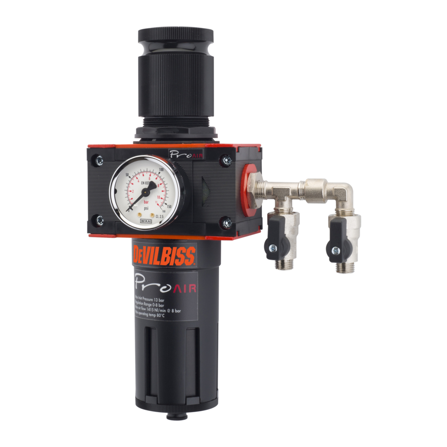
PRO AIR is a range of compact compressed air regulator and filters suitable for 1 or 2 operators. PRO AIR 2 and 3 are suitable for use with Respiratory Personal Equipment such as the Devilbiss PRO VISOR and Half Mask kits.
| PRO AIR 1 | Filter - Incoming air is rotated by a centrifuge unit to remove the heaviest liquid and solid particles. The remaining solid particles are collected by a porous filter to 5µm. The accumulated liquid can be drained using the plug in the base of the bowl. Regulator - This allows the input pressure to be reduced to a stable output pressure following initial filtering. |
| PRO AIR 2 | as above, but to include a Coalescer - This removes the smallest amounts of liquid and solids down to 0.01µm. The liquid droplets are captured on micro fibres, these form larger droplets and collect in the bowl which can be drained using the plug at the base of the bowl. |
| PRO AIR 3 | as above, but to include an Activated Carbon element - This element filters in a similar way to the coalescer, but will remove oil carry over to 0.003 ppm. |
Shut of valves - Each of the 2 outlets can be isolated independently.
SPECIFICATIONS
| PROAIR-1 | PROAIR-2 | PROAIR-3 | |||
| Air Supply Connection | 1/2" BSP female | ||||
| Air Outlet Connections | 1/4" BSP male x 2 with shut off valve | ||||
| Gauge port | 1/8" BSP female | ||||
| Gauge range | 0- 11 bar (0- 160psi) | ||||
| Size: | Width | 185 | 330 | 395 | |
| Height | 280 | 280 | 280 | ||
| Weight | 2300g | 3375g | 4205g | ||
| Maximum: | Air flow | 3500 l/min | 900 l/min | 900 l/min | |
| Air supply pressure | 13 bar | ||||
| Regulated air pressure | 0- 8 bar | ||||
| Operating temperature | 80°C | ||||
| Degree of filtration: | Output air quality class ISO8573-1: | 3.7.4 | 1.7.2 | 1.7.1 | |
| Element Life | 1000 Hours | ||||
| Filter condensate/ Coalescer drain | Semi-Automatic | ||||
| Product Description/Object of Declaration: | Pro Air 1, 2, 3 | ||||
| Suitable for use in hazardous area: | Zone 1 | ||||
| Protection Level: Notified body details and role: | II 2G IIB D c T5 | ||||
| This Declaration of conformity/ incorporation is issued under the sole responsibility of the manufacturer: | Finishing Brands UK Ltd, Ringwood Road, Bournemouth, BH11 9LH. UK | ||||
In this part sheet, the words WARNING, CAUTION and NOTE are used to emphasise important safety information as follows:
 |  |  NOTE NOTE |
| Hazards or unsafe practices which could result in severe personal injury, death or substantial property damage. | Hazards or unsafe practices which could result in minor personal injury, product or property damage. | Important installation, operation or maintenance information. |
Read the following warnings before using this equipment.

READ THE MANUAL. Before operating finishing equipment, read and understand all safety, operation and maintenance information provided in the operation manual. Users must comply with all local and national codes of practice and insurance company requirements governing ventilation, fire precautions, operation and house-keeping of working areas.

STATIC CHARGE. Fluid may develop a static charge that must be dissipated through proper grounding of the equipment, objects to be sprayed and all other electrically conductive objects in the dispensing area. Improper grounding or sparks can cause a hazardous condition and result in fire, explosion or electric shock and other serious injury.

LOCK OUT / TAG-OUT. Failure to de-energise, disconnect, lock out and tagout all power sources before performing equipment maintenance could cause serious injury or death.

INSPECT THE EQUIPMENT DAILY. Inspect the equipment for worn or broken parts on a daily basis. Do not operate the equipment if you are uncertain about its condition.

OPERATOR TRAINING. All personnel must be trained before operating finishing equipment.

KNOW WHERE AND HOW TO SHUT OFF THE EQUIPMENT IN CASE OF AN EMERGENCY.

PROJECTILE HAZARD. You may be injured by venting liquids or gases that are released under pressure, or flying debris.
EQUIPMENT MISUSE HAZARD. Equipment misuse can cause the equipment to rupture, malfunction or start unexpectedly and result in serious injury.

PRESSURE RELIEF PROCEDURE. Always follow the pressure relief procedure in the equipment instruction manual.

WEAR SAFETY GLASSES. Failure to wear safety glasses with side shields could result in serious eye injury or blindness.

NEVER MODIFY THE EQUIPMENT. Do not modify the equipment unless the manufacturer provides written approval.
IT IS THE RESPONSIBILITY OF THE EMPLOYER TO PROVIDE THIS INFORMATION TO THE OPERATOR OF THE EQUIPMENT.
PARTS LIST
| REF. | PART No. | DESCRIPTION |  |  |  |
| 1 | PROAIR-51 | FILTER ELEMENT (5µm) | 1 | 1 | 1 |
| 2 | PROAIR-52 | COALESCAR FILTER ELEMENT (0.01µm) | X | 1 | 1 |
| 3 | PROAIR-53 | ACTIVATED CARBON FILTER ELEMENT | X | X | 1 |
| PROAIR-62 | KIT OF PROAIR-51 & 52 | X | 1 | X | |
| PROAIR-63 | KIT OF PROAIR-51, 52 & 53 | X | X | 1 | |
| 4 | PROAIR-71 | UPPER COVER ASSEMBLY | 1 | 1 | 1 |
| 5 | PROAIR-72 | METAL FILTER BOWL WITH DRAIN VALVE | 1 | 2 | 3 |
| 6 | SER-3414-MF | BALL VALVE 1/4" BSP (M) & (F) | 2 | 2 | 2 |
| 7 | GA-319 | PRESSURE GAUGE 0-160 psi | 1 | 1 | 1 |
| 8 | DV-8000035 | ISOLATION VALVE 1/2" | X | 1 | 1 |
EXPLODED VIEW

INSTALLATION
- Do not install the unit above electrical or any other equipment that could be damaged by discharged condensate oil.
- Ensure air flows through the unit in the direction of the arrows on the body.
- Install the unit as near as possible to the point of use.
- An isolation valve is fitted (8) to the inlet of the PRO AIR 2 & 3 for convenience when maintaining and to release condensate and oil from bowl. (see operation) Slide to the right towards the regulator to open. Slide to the left to close.
- The unit should be mounted in an upright position.
- Ensure the regulator is correctly earthed using the marked wall bracket on the outlet side of the unit as the earthing point as shown below and verify continuity from each Ball Valve (6) to another known earth point. A resistance of less than 1 K ohms should be achieved for dissipation of electrostatic charge. PRO AIR-2 shown.
![]()

OPERATION
- Do not exceed the maximum working pressures and temperatures.
- When regulating the pressure always adjust from a lower pressure increasing to the desired pressure, rather than from a higher pressure down.
- To lock the set pressure depress the knob which prevents it being adjusted. To release the lock lift the knob up.
- The drain valve on the bottom of the filter and coalescer can be used manually or semi- automatically.
- Semi-Automatic - The valve push button is rotated to the left, in this mode when the air pressure is exhausted from the unit the push button opens under spring operation.
- Manually - The valve push button rotated to the right shuts off the drain permanently, until it is rotated to the left when it can be pushed up to drain even when the unit is pressurized.
MAINTENANCE
Always de-pressurise the whole unit prior to carrying out any maintenance work, ensuring no pressure is locked in the unit or items attached to it. The regulator knob should be wound fully counter clockwise to exhaust all pressure after isolating.
Ensure earthing of the unit is not affected by maintenance activities, see Installation.
Filter - To replace these items unscrew and remove bowl, unscrew the central bolt and pull the filter down.
Coalescer/ Activated carbon filter - To replace this item, unscrew and remove the bowl, then unscrew the filter element. Care should be taken when replacing the element not to cross the threads.
Gauge - When replacing this item, screw a new gauge in by hand only, do not use a spanner. Seal the thread using a liquid sealant, do not use PTFE tape.
Filter/ Coalescer/ Activated carbon filter periods for replacement
It is recommended that filter elements are replaced periodically i.e. when a drop in pressure is noticeable through the unit or every 6 months or 1000 hours use.
Do not use solvents or aggressive chemicals to clean the unit, which may affect the materials of construction.
Always use recommended and original parts and accessories.
For technical assistance or to locate an authorised distributor, contact one of our international sales and customer support locations below.
USA/Canada
www.devilbiss.com
info@carlisleft.com
Toll Free Tel: 1-800-992-4657
Toll Free Fax: 1-888-246-5732
United Kingdom
www.carlisleft.eu
info@carlisleft.eu
Tel: +44 (0)1202 571 111
Fax: +44 (0)1202 573 488
Documents / Resources
References

Download manual
Here you can download full pdf version of manual, it may contain additional safety instructions, warranty information, FCC rules, etc.
Advertisement


Need help?
Do you have a question about the PRO AIR Series and is the answer not in the manual?
Questions and answers