Advertisement
Introduction
Areas of application
Education and teaching: Use in schools, universities and training institutions to teach the basics of electronics, programming and embedded systems. Research and development: Use in research and development projects to create prototypes and experiments in the fields of electronics and computer science. Prototype development: Use in the development and testing of new electronic circuits and devices. Hobby and Maker Projects: Used by electronics enthusiasts and hobbyists to develop and implement DIY projects.
Required knowledge and skills
Basic understanding of electronics and electrical engineering. Knowledge of programming, especially in the C/C++ programming language. Ability to read schematics and design simple circuits. Experience working with electronic components and soldering.
Operating conditions
The product may only be operated with the voltages specified in the data sheet to avoid damage. A stabilized DC power source is required for operation. When connecting to other electronic components and circuits, the maximum current and voltage limits must be observed to avoid overloads and damage.
Environmental conditions
The product should be used in a clean, dry environment to avoid damage caused by moisture or dust. Protect the product from direct sunlight (UV)
Intended Use
The product is designed for use in educational, research and development environments. It is used to develop, program and prototype electronic projects and applications. The Sensor product is not intended as a finished consumer product, but rather as a tool for technically savvy users, including engineers, developers, researchers and students.
Improper foreseeable use
The product is not suitable for industrial use or safety-relevant applications. Use of the product in medical devices or for aviation and space travel purposes is not permitted
RFID means radio-frequency identification. RFID uses electromagnetic fields to transfer data over short distances. RFID tags are used in many industries, for example, an RFID tag attached to an automobile during production can be used to track its progress through the assembly line, RFID-tagged pharmaceuticals can be tracked through warehouses, implanting RFID microchips in livestock and pets allows positive identification of animals, etc.
An RFID system is made of of two parts: a tag and a reader. RFID tags are embedded with a transmitter and a receiver. The RFID component on the tags have two parts: a microchip that stores and processes information, and an antenna to receive and transmit a signal. The tag contains the specific serial number for one specific object and it does not need to be within direct line-of-sight of the reader to be tracked.
To read the information encoded on a tag, a radio transmitter-receiver called a reader emits a signal to the tag using an antenna. The tag responds with the information written in its memory bank. The reader will then transmit the read results to a microcontroller.
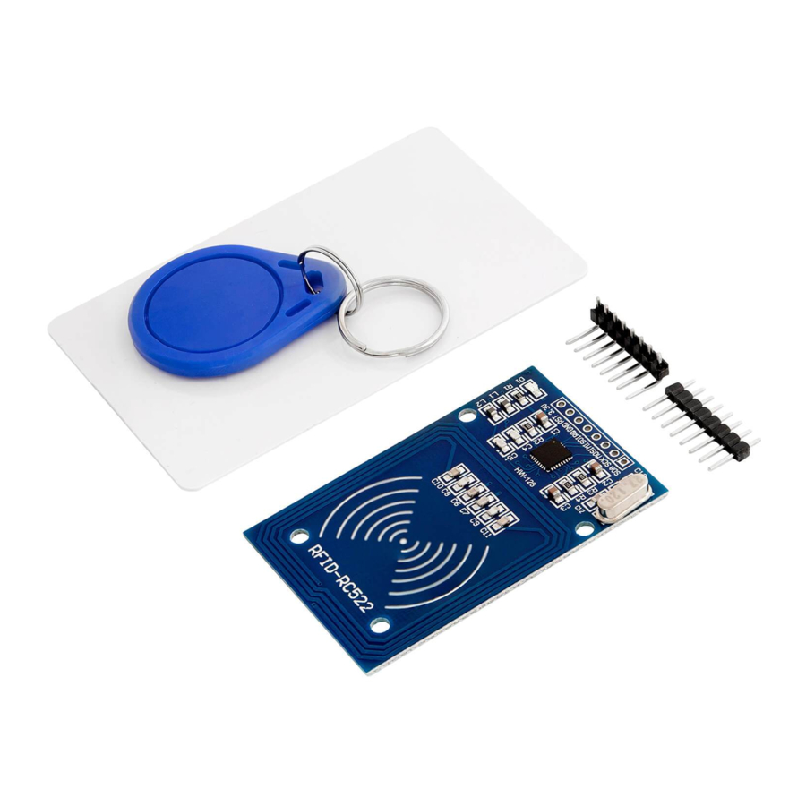
Specifications
- Chip: MFRC522
- Operating frequency: 13.56MHz
- Power supply voltage: 3.3V
- Current: 13 - 26mA
- Read Range: Approx 30mm
- Communication: SPI interface
- Max Data Transfer Rate: 10Mbit/s
- Dimensions: 40 x 60mm [1.6 x 2.4in]
The reader is a near-field device, not an actual radio. The way the reader works is not by sending and receiving radio signals, but by detecting small change in impedance of the tuned antenna circuit caused by the RFID tag modulating its tuned circuit. Move the RFID tag out from the near field of the antenna and there is no effect to measure. The reader is not really a receiver, but an amplified version of the fluctuations of the average output voltage in the tuned circuit.
The pinout of the reader

Power supply voltage is 3.3V! Do not connect 5V to this pin, or else you could destroy the device!
The reader uses SPI interface to communicate with a microcontroller.
Interrupt IRQ pin is on HIGH state all the time, and when the interrupt event happens, it changes its state to LOW for a brief period of time. Interrupt event happens when RFID tag is detected in the near-field of the reader.
How to set-up Arduino IDE
If you did not install Arduino IDE already, this is how to do it. Go to the link: https://www.arduino.cc/en/Main/Software and download installation file for your operating system platform.

For Windows, double click on downloaded ".exe" file and follow instructions in installation window.
For Linux, download file with extension ".tar.xz", which then you need to extract. When you extract it, go to the extracted directory, and open terminal in that directory. You need to run two ".sh" scripts, first called "arduino-linux setup.sh", and second called "install.sh".
To run first script in terminal, run the following command:
sh arduino-linux-setup.sh user_name
user_name - is the name of super user in the Linux operating system. After this, you will be prompted to provide password for the super user. Wait for a few minutes for script to complete everything.
After installation of the first script, run the second called "install.sh" script. In terminal, run the following command:
sh install.sh
After the installation of these scripts, go to the All Apps to find the Arduino IDE installed.

Next thing is to check if your PC can detect the ATmega328p board. Open freshly installed Arduino IDE, and go to:
Tools > Board > {your board name here}
{your board name here} should be the Arduino/Genuino Uno, as you can see on the image below:

After this you need to select the port on which the microcontroller board is connected. Go to: Tools > Port > {port name goes here}
If you connected the ATmega328p board on the USB port, there should be several port names. Because we are using Arduino IDE on Windows, port names are like on image below:

For Linux users, port name is "/dev/ttyUSBx" for example, where "x" represents specific integer number between 0 and for example 9, for instance.
Connecting the reader with ATmega328p
Connect the reader with the ATmega328p as shown on the connection diagram below:

| Module pin | > ATmega328p pin | |
| 3.3V | > 3.3V! | Red wire |
| RST | > D9 | Purple wire |
| GND | > GND | Black wire IRQ |
| > D2 | Ochre wire | |
| MISO | > D12 | Orange wire |
| MOSI | > D11 | Green wire |
| SCK | > D13 | Blue wire |
| SDA (SS) | > D10 | Gray wire |
The library for Arduino IDE
To use the module with ATmega328p it is recommended to download and install library for it. Open Arduino IDE and go to: Tools > Manage Libraries. New window will open, type "RFID 522" in the search box, and install library called "MFRC522" made by "GithubCommunity", as shown on the image below:

With the library comes many example sketches. We will use one example sketch, called "MinimalInterrupt". To open it, go to:
File > Examples > MFRC522 > MinimalInterrupt
Sketch example


When you upload the sketch to the ATmega328p, open Serial Monitor, (Tools > Serial Monitor). The output should look like the output on the image below:

When you bring RFID Card or Chip near the reader, an interrupt happens, and the UID number of the Card/Chip is sent to the Serial Monitor.
At the beginning of the sketch two libraries are imported, SPI for SPI interface and MFRC522 for RFID reader. Then three macros are created, one for reset pin number, second for slave select pin number and last for interrupt pin number.
After that "mfrc522" object, which represents the reader in the software and key variable are created. The key variable is used to store UID number of the specific card.
Then the bNewInt variable is created. When interrupt happens, the state of bNewInt variable changes to true, which indicates that interrupt happened. Then in the code we check for the state of bNewInt variable and print the corresponding output to the Serial Monitor (more about this later in the text).
Then we create regVal variable, which is used to set-up registers of the chip in the RFID reader.
In the setup() function, first we set-up Serial Interface with baud rate of 9600. After, we set-up SPI interface and initialize the mfrc522 object.
Later we output the MFRC522 reader version on the Serial Monitor. Valid numbers are 0x91 and 0x92.
Then we set-up pin mode of the interrupt pin to INPUT with internal PULL UP resistor. After this, we attach the interrupt routine with following line of the code:
attachInterrupt(digitalPinToInterrupt(IRQ_PIN), readCard, FALLING)
Where the first argument is a built-in function:
digitalPinToInterrupt()
which sets the IRQ_PIN (digital I/O pin 2), to listen for interrupt event. The second argument is the function that will be executed when an interrupt happens. And the third argument is the edge of digital signal, which represents the interrupt event itself.
For the purpose of this example we are using FALLING edge of the digital signal, that comes on the IRQ_PIN, as interrupt event. The value of this argument can also be RISING or BOTH, but we are not using that in our example.
At the end of setup() function we clear wrong interrupt readings with following lines of the code:
do {; } while (!bNewInt);
bNewInt = false;
In the loop() function there is one if statement, where we check the state of bNewInt variable. If bNewInt state is true, then interrupt happened, and we print output to the Serial Monitor. Output contains the message "Interrupt. Card UID: number", where number is the UID number of the RFID card that caused interrupt. At the end of the if statement, we set the bNewInt variable to false.
At the end of loop() function, we set-up registers of the reader chip again, and wait for 100 milliseconds.
After loop() function, we create readCard() function, which is executed when the interrupt happens. In the readCard() function we only set the state of bNewInt variable to true. After this we create three functions which are used to set-up registers of the reader chip, and to communicate with the reader.
Connecting the reader with Raspberry Pi
Connect the reader with Raspberry Pi as shown on the connection diagram below:

| Module pin | > Raspberry Pi pin | |
| SDA (SS) | > GPIO8 [pin 24] | Gray wire SCK |
| > GPIO11 [pin 23] | Blue wire | |
| MOSI | > GPIO10 [pin 19] | Green wire |
| MISO | > GPIO9 [pin 21] | Orange wire |
| IRQ | > GPIO24 [pin 18] | Ochre wire |
| GND | > GND [pin 25] | Black wire |
| RST | > GPIO25 [pin 22] | Purple wire |
| 3.3V | > 3V3 [pin 1] | Red wire |
The library for Python
In order to use the reader with the Raspberry Pi it is recommended to download a library for Python. The library we are going to use is called "pi rc522". To install this library, open a terminal and run the following commands, one by one:
sudo apt-get update
sudo apt-get upgrade
sudo pip3 install pi-rc522
Now we are ready to start making Python script.
Python script

Save the script by the name "rfid.py" into default script directory. To run the script open terminal in the directory where you saved the script and run the following command:
python3 rfid.py
The output should look like the output on the image below:

To end the script press "CTRL + C".
At the beginning of the script we import two libraries, one called pirc522 that we just installed and the other is for time.
Then we create reader object, using the following line of the code:
reader = RFID()
You can connect the SDA pin of the reader to CE1 (GPIO7 [pin 26]) instead of CE0 (GPIO8 [pin 24]). When you do that you have to create reader object with the following line of the code:
reader = RFID(bus=0, device=1)
Also, you can connect RST pin to any other free GPIO pin. If you do this you have to create reader object with the following line of the code: reader = RFID(pin_rst=number)
Where number is the Raspberry Pi board pin number (not GPIO number, but pin number).
Furthermore, you can connect the IRQ pin to any other free GPIO pin. If you do this you have to create reader object with the following line of the code: reader = RFID(pin_irq=number)
Where number is the Raspberry Pi board pin number (not GPIO number, but pin number).
After this we create a list called keys where we store new UID keys. Also we create a boolean variable called key_read used to check if key is already in the keys list.
Then we create try-except-finally block. We do this in order to detect keyboard interrupt. Keyboard interrupt happens when we press CTRL + C on the keyboard. finally part of try-except-finally block is used to clean the GPIO pins of any used interfaces or defined pin modes after keyboard interrupt.
In the try part of try-except-finally block we create infinite loop (while True:). In this loop first we wait for tag to be detected. When tag is detected, an interrupt will happen on IRQ_PIN. When interrupt happens, we can read the tag data.
reader.request() function returns a tuple of two elements. The first element is a boolean value representing error (True there is error, False there is no error), and the second element represents the type of tag (which we do not use in the script).
Then we check if there is an error. If there are no errors we proceed to read UID of the tag.
reader.anticoil() function returns a tuple of two elements. The first element is a boolean value representing error (True there is error, False there is no error), and the second element is the UID number of the tag.
Then, again we check if there is an error while reading UID. If there are no errors we proceed with checking if UID number is already in the keys list. If the UID number is not in the keys list, we add a new number, and print message "New tag detected! UID: number", where number is UID number of the tag. If UID number of the tag is in the keys list, we print message "Already detected that tag!".
When we are done with reading data sent by reader, we have to run the following function:
reader.stop_crypto()
At the end of infinite loop block we call sleep(0.1), or waiting time interval of 100 milliseconds, a waiting time interval between two loops of the infinite loop block.
You've done it!
Now you can use your module for various projects.
Safety instructions
Although our product complies with the requirements of the RoHS Directive (2011/65/EU) and does not contain any hazardous substances in quantities above the permitted limits, residues may still be present. Observe the following safety instructions to avoid chemical hazards:

Soldering can produce fumes that can be harmful to health.
Note: Use a solder fume extractor or work in a well-ventilated area. If necessary, wear a respirator mask.
Some people may be sensitive to certain materials or chemicals contained in the product.
Note: If skin irritation or allergic reactions occur, stop use and, if necessary, consult a doctor.
Keep the product out of the reach of children and pets to avoid accidental contact and swallowing of small parts.
Note: Store the product in a safe, closed container when not in use.
 Attention: Avoid contact of the product with food and drinks.
Note: Do not store or use the product near food to prevent contamination.
The product contains sensitive electronic components and sharp edges. Improper handling or assembly can result in injury or damage. Observe the following safety instructions to avoid mechanical hazards:
Attention: The product's circuit board and connectors may have sharp edges. Use caution to avoid cuts.
Note: Wear appropriate protective gloves when handling and assembling the product.
Avoid excessive pressure or mechanical stress on the board and components.
Note: Only mount the product on stable and flat surfaces. Use appropriate spacers and housings to minimize mechanical stress.
Attention: Make sure the product is securely fastened to prevent accidental slipping or falling.
Note: Use appropriate support or secure mounting in enclosures or on mounting plates.
Make sure all cable connections are connected securely and correctly to avoid strain and accidental unplugging.
Note: Route cables so that they are not under tension and do not pose a tripping hazard.
The product operates with electrical voltages and currents that, if used improperly, can result in electric shocks, short circuits or other hazards. Observe the following safety instructions to avoid electrical hazards:
Attention: Use the product only with the specified voltages.
Note: The performance limits of the product can be found in the associated data sheet.

Avoid short circuits between the connectors and components of the product.
Note: Make sure that no conductive objects touch or bridge the circuit board. Use insulated tools and pay attention to the arrangement of connections.
Do not perform any work on the product when it is connected to a power source.
Note: Disconnect the product from power before making any circuit changes or connecting or removing components.
Do not exceed the specified current ratings for the product's inputs and outputs.
Note: The performance limits of the product can be found in the technical specifications or in the data sheet.
Attention: Make sure that the power sources used are stable and correctly sized.
Note: Only use tested and suitable power supplies to avoid voltage fluctuations and overloads.
Attention: Maintain sufficient distance from live parts to avoid accidental contact.
Note: Ensure that the cabling is arranged safely and clearly according to the voltage used.
Use insulating housings or protective covers to protect the product from direct contact.
Note: Place the product in a non-conductive case to avoid accidental touching and short circuits.
The product and the components on it may become warm during operation. Improper handling or overloading the product can result in burns, damage or fire. Observe the following safety instructions to avoid thermal hazards:
Make sure the product is used within recommended operating temperatures.
Note: The recommended operating temperature range is typically between -40°C and +85°C. Check the specific information in the product data sheet.
Attention: Do not place the product near external heat sources such as radiators or direct sunlight.
Note: Ensure that the product is operated in a cool and well-ventilated area.
Attention: Make sure the product is well ventilated to avoid overheating.
Note: Use fans or heat sinks when operating the product in a closed enclosure or in an environment with limited air circulation.
Attention: Mount the product on heat-resistant surfaces and in heat-resistant housings.
Note: Use enclosure materials that can withstand high temperatures to avoid damage or fire hazard.
Implement temperature monitoring when using an enclosure and, if necessary, protection mechanisms that shut down the product if it overheats.
Note: Use temperature sensors and appropriate software to monitor the temperature of the product and shut down the system if necessary.
Avoid overloads that can cause excessive heating of components.
Note: To prevent overheating, do not exceed the specified current and voltage limits.
Short circuits can generate significant heat and cause fires.
Note: Make sure that all connections are correct and secure and that no conductive objects can accidentally cause short circuits.
Now is the time to learn and make the Projects on your own. You can do that with the help of many example scripts and other tutorials, which you can find on the internet.
If you are looking for the high quality microelectronics and accessories, AZ-Delivery Vertriebs GmbH is the right company to get them from. You will be provided with numerous application examples, full installation guides, eBooks, libraries and assistance from our technical experts.
https://az-delivery.de
Have Fun!
Impressum
https://az-delivery.de/pages/about-us
Documents / Resources
References
![www.arduino.cc]() https://www.arduino.cc/en/Main/Software
https://www.arduino.cc/en/Main/Software![az-delivery.de]() AZ-Delivery - Ihr Experte für Mikroelektronik
AZ-Delivery - Ihr Experte für Mikroelektronik![az-delivery.de]() Impressum / Disclaimer
Impressum / Disclaimer
Download manual
Here you can download full pdf version of manual, it may contain additional safety instructions, warranty information, FCC rules, etc.
Advertisement


Need help?
Do you have a question about the RFID RC522 and is the answer not in the manual?
Questions and answers