
Related Manuals for AZ-Delivery D1 Mini


Summary of Contents for AZ-Delivery D1 Mini
- Page 1 Welcome! Thank you for purchasing our AZ-Delivery D1 Mini ESP8266 module. On the following pages, you will be introduced to how to use and set-up this handy device. Have fun!
-
Page 2: Table Of Contents
Serial ......................7 The I2C ....................8 SPI ......................8 The pinout....................9 D1 Mini module - Software ................. 10 Digital I/O pins ..................10 Analog input pin ..................11 Serial communication ................12 The I2C and SPI interfaces ..............12 Sharing CPU time with the RF part ............ -
Page 3: Introduction
Arduino boards before, then this is really easy for you. Just keep in mind that it is not limited to this option, there are many other ways to program the D1 Mini module (official ESP SDK for C programming, Lua interpreter, MicroPython firmware, are few of many). -
Page 4: Specifications Of The Esp8266
Specifications of the ESP8266 » 802.11 b/g/n » Integrated low power 32-bit MCU » Integrated 10-bit ADC » Integrated TCP/IP protocol stack » Integrated TR switch, balun, LNA, power amplifier and matching network » Integrated PLL, regulators, and power management units »... -
Page 5: The D1 Mini Module
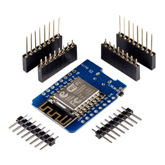
The D1 Mini module The D1 Mini module comes unsoldered with pair of eight pin male headers, a pair of eight pin female headers and a pair of eight pin female headers with extra long legs (which can be seen on the cover image). -
Page 6: Digital I/O Pins
Digital I/O pins Just like any Arduino board, the D1 Mini module has digital input/output pins or GPIO - General Purpose Input/Output pins. As the name implies, it can be used as digital inputs to read a digital voltage, or as digital outputs to output either 0V (sink current) or 3.3V (source current). -
Page 7: Pwm
1kHz). Analog input The D1 Mini module has a single analog input, with an input voltage range of 0V - 3.0V. If more than 3.3V is applied, the chip could be damaged. The analog to digital converter (ADC) has a resolution of 10 bits. -
Page 8: The I2C
The I2C The D1 Mini module does not have a hardware I2C or TWI (Two Wire Interface), but it is implemented in software. This means that any two digital pins can be used as the I2C pins. By default, the I2C library uses GPIO4 as SDA and GPIO5 as SCL (the datasheet specifies GPIO2 as SDA and GPIO14 as SCL). -
Page 9: The Pinout
The pinout The D1 Mini module has two rows of eight pins (sixteen pins in total). The pinout of the module is shown on the following image: - 9 -... -
Page 10: D1 Mini Module - Software
D1 Mini module - Software Most of the microcontroller functionality of the ESP uses exactly the same syntax as a normal Arduino board, making it really easy to get started. Digital I/O pins Just like with a regular Arduino board, the pin function can be set using the... -
Page 11: Analog Input Pin
Just like on any Arduino board, function analogRead(A0) can be used to get the analog voltage on the analog input (0 = 0V, 1023 = 1.0V). The D1 Mini module can also use the ADC to measure the supply voltage (VCC). To do this, include ADC_MODE(ADC_VCC) at the top of your sketch, and use ESP.getVcc() to actually get the voltage. -
Page 12: Serial Communication
Serial communication To use UART0 (TX = GPIO1, RX = GPIO3), use the Serial object, just like on an Arduino board: Serial.begin(baud_reate) To use the alternative pins (TX = GPIO15, RX = GPIO13), use the following line of code: Serial.swap() after Serial.begin() To use UART1 (TX = GPIO2), use the Serial1 object. -
Page 13: Sharing Cpu Time With The Rf Part
Sharing CPU time with the RF part One thing to keep in mind while writing programs for the D1 Mini module (ESP8266) is that the sketch has to share resources (CPU time and memory) with the wifi and TCP-stacks (the software that runs in the background and handles all wifi and IP connections). -
Page 14: How To Set-Up Arduino Ide
How to set-up Arduino IDE If the Arduino IDE is not installed, follow the and download the installation link file for the operating system of choice. Windows users, double click on the downloaded .exe file and follow the instructions in the installation window. - 14 -... - Page 15 For Linux users, download a file with the extension .tar.xz, which has to be extracted. When it is extracted, go to the extracted directory and open the terminal in that directory. Two .sh scripts have to be executed, the first called arduino-linux-setup.sh and the second called install.sh.
- Page 16 Almost all operating systems come with a text editor preinstalled (for example, Windows comes with Notepad, Linux Ubuntu comes with Gedit, Linux Raspbian comes with Leafpad, etc.). All of these text editors are perfectly fine for the purpose of the eBook. Next thing is to check if your PC can detect an Arduino board.
- Page 17 If the Arduino IDE is used on Windows, port names are as follows: For Linux users, for example port name is /dev/ttyUSBx, where x represents integer number between 0 and 9. - 17 -...
-
Page 18: D1 Mini With Arduino Ide
D1 Mini with Arduino IDE To set-up the Arduino IDE so that the D1 Mini module can be programmed via the Arduino IDE, follow the next steps. The first thing to do is to install the USB driver, which can be downloaded here. - Page 19 If there are one or more links inside Additional URLs field, just add one comma after the last link, paste a new link after a comma and click the OK button. Then close the Arduino IDE. Open Arduino IDE again and go to: Tools >...
- Page 20 The next step is to select the right board in the Arduino IDE. Open Arduino IDE and go to: Tools > Board > {board name} and select the first Generic ESP8266 Module as shown on the following image: - 20 -...
- Page 21 After that, select the port on which the D1 Mini module board is connected. Go to: Tools > Port > {port name goes here} If the D1 Mini module board is connected on the USB port, there should be some port names. In this eBook the Arduino IDE is used on Windows, port names are as follows: For Linux users, port name is /dev/ttyUSBx for example, where “x”...
-
Page 22: Blink + Pwm + Serial Sketch Examples
// Wait for two seconds For the D1 Mini module, LED_BUILTIN is equal to a number 2, which means that on-board LED is connected to the GPIO2 pin. To turn ON the LED the GPIO2 pin has to be put in the LOW state, and to turn it OFF the GPIO2 pin has to be put in the HIGH state. -
Page 23: Software Pwm Sketch Example
Software PWM sketch example brightness = 1; // do not set it to the zero // zero disables the PWM on a specific pin uint8_t fadeAmount = 5; void setup() { pinMode(LED_BUILTIN, OUTPUT); void loop() { analogWrite(LED_BUILTIN, 200); // high brightness delay(1000);... - Page 24 Arduino boards is used: analogWrite(pin, value) where pin is the name of GPIO pin, any free GPIO pin of the D1 Mini module. The value is the duty cycle, a value between 1 and 1023. Do not use number zero for value, because it turns OFF the PWM function...
-
Page 25: Serial Communication Sketch Example
{ Serial.println("Hello from the D1 Mini module!"); delay(1000); Upload the sketch to the D1 Mini module and open the Serial Monitor (Tools > Serial Monitor). The result should look like the on the following image: - 25 -... - Page 26 With the ESP8266 board library comes many other sketch examples. The wifi part of the D1 Mini module could be tested from there. It is not covered in this eBook. - 26 -...
- Page 27 If you are looking for the high quality products for Arduino and Raspberry Pi, AZ-Delivery Vertriebs GmbH is the right company to get them from. You will be provided with numerous application examples, full installation guides, eBooks, libraries and assistance from our technical experts.
Need help?
Do you have a question about the D1 Mini and is the answer not in the manual?
Questions and answers