
Related Manuals for AZ-Delivery GY-521 MPU-6050


Summary of Contents for AZ-Delivery GY-521 MPU-6050
- Page 1 Welcome! Thank you for purchasing our AZ-Delivery GY-521 MPU-6050 3-axis Gyroscope and Acceleration sensor module. On the following pages, you will be introduced to how to use and set-up this handy device. Have fun! - 1 -...
- Page 2 Areas of application Education and teaching: Use in schools, universities and training institutions to teach the basics of electronics, programming and embedded systems. Research and development: Use in research and development projects to create prototypes and experiments in the fields of electronics and computer science. Prototype development: Use in the development and testing of new electronic circuits and devices.
- Page 3 consult a doctor. Caution: Keep the product out of the reach of children and pets to avoid accidental contact and swallowing of small parts. Note: Store the product in a safe, closed container when not in use. Attention: Avoid contact of the product with food and drinks.
-
Page 4: Table Of Contents
Table of Contents Introduction....................3 Specifications....................4 Features......................5 Gyroscope Features..................5 Accelerometer Features................6 The pinout.....................7 How to set-up Arduino IDE................8 How to set-up the Raspberry Pi and Python..........12 Connecting the module with Atmega328P Board........13 Sketch example..................14 Connecting the module with Raspberry Pi..........18 Library and tools for Python..............19 Enabling the I2C interface................20 Python script....................22 - 2 -... -
Page 5: Introduction
Introduction The GY-521 is a module based on MPU6050 sensor chip which is a system that combines a 3-axis gyroscope, a 3-axis accelerometer and a digital thermometer. Its special feature is the built-in hardware DMP (Digital Motion Processor) unit, which facilitates the conversion of processed data from all three sensors to a specific position relative to the Earth, thus relieving the microcontroller. -
Page 6: Specifications
Specifications Operating input voltage` 3V to 5V Operating current 4mA ( max.) Gyroscope operating current 3.6mA Accelerometer operating current 500µA Gyroscope range: +/- 250 500 1000 2000 degree/sec Acceleration range +/- 2g, +/- 4g, +/- 8g, +/- 16g Communication interface G-Force tolerance 10,000g (up to 0.2ms) ADC Internal converter... -
Page 7: Features
Features Gyroscope Features The triple-axis MEMS gyroscope in the MPU6050 includes a wide range of features: • Digital-output X-, Y-, and Z-Axis angular rate sensors (gyroscopes) with a user-programmable full-scale range of ±250, ±500, ±1000, and ±2000°/sec • External sync signal connected to the FSYNC pin supports image, video and GPS synchronization •... -
Page 8: Accelerometer Features
Accelerometer Features The triple-axis MEMS accelerometer in MPU-60X0 includes a wide range of features: • Digital-output triple-axis accelerometer with a programmable full scale range of ±2g, ±4g, ±8g and ±16g • Integrated 16-bit ADCs enable simultaneous sampling of accelerometers while requiring no external multiplexer •... -
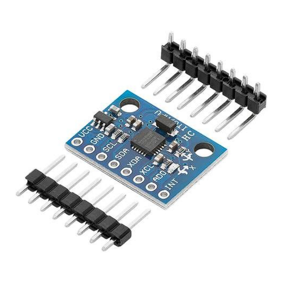
Page 9: The Pinout
The pinout The module has eight pins. The pinout is shown on the following image: INT - This is the interrupt pin. You can setup the MPU6050 to pull this low when certain conditions are met such as new measurement data being available. -
Page 10: How To Set-Up Arduino Ide
How to set-up Arduino IDE If the Arduino IDE is not installed, follow the link and download the installation file for the operating system of choice. The Arduino IDE version used for this eBook is 1.8.13. For Windows users, double click on the downloaded .exe file and follow the instructions in the installation window. - Page 11 For Linux users, download a file with the extension .tar.xz, which has to be extracted. When it is extracted, go to the extracted directory and open the terminal in that directory. Two .sh scripts have to be executed, the first called arduino-linux-setup.sh and the second called install.sh.
- Page 12 Almost all operating systems come with a text editor preinstalled (for example, Windows comes with Notepad, Linux Ubuntu comes with Gedit, Linux Raspbian comes with Leafpad, etc.). All of these text editors are perfectly fine for the purpose of the eBook. Next thing is to check, if your PC can detect a microcontroller board.
- Page 13 If the Arduino IDE is used on Windows, port names are as follows: For Linux users, for example port name is /dev/ttyUSBx, where x represents integer number between 0 and 9. - 11 -...
-
Page 14: How To Set-Up The Raspberry Pi And Python
How to set-up the Raspberry Pi and Python For the Raspberry Pi, first the operating system has to be installed, then everything has to be set-up so that it can be used in the Headless mode. The Headless mode enables remote connection to the Raspberry Pi, without the need for a PC screen Monitor, mouse or keyboard. -
Page 15: Connecting The Module With Atmega328P Board
Connecting the module with Atmega328P Board Connect the module with the microcontroller board as shown on the following connection diagram: Module pin Microcontroller pin Wire color Red Wire Black Wire Blue wire Green wire - 13 -... -
Page 16: Sketch Example
Sketch example #include <Wire.h> #include <math.h> const int MPU = 0x68; int16_t AcX, AcY, AcZ, Tmp, GyX, GyY, GyZ; AcXcal, AcYcal, AcZcal, GyXcal, GyYcal, GyZcal, tcal; double t, tx, tf, pitch, roll; void setup() { Wire.begin(); Wire.beginTransmission(MPU); Wire.write(0x6B); Wire.write(0); Wire.endTransmission(true); Serial.begin(9600);... - Page 17 GyX = Wire.read() << 8 | Wire.read(); GyY = Wire.read() << 8 | Wire.read(); GyZ = Wire.read() << 8 | Wire.read(); tx = Tmp + tcal; t = tx / 340 + 36.53; tf = (t * 9 / 5) + 32; getAngle(AcX, AcY, AcZ);...
- Page 18 void getAngle(int double x = Ax; double y = Ay; double z = Az; pitch = atan(x / sqrt((y * y) + (z * z))); roll = atan(y / sqrt((x * x) + (z * z))); pitch = pitch * (180.0 / 3.14); roll = roll * (180.0 / 3.14) ;...
- Page 19 Upload the sketch to the microcontroller board and run the Serial Monitor (Tools > Serial Monitor). The result should look like as on the following image: - 17 -...
-
Page 20: Connecting The Module With Raspberry Pi
Connecting the module with Raspberry Pi Connect the module with the Raspberry Pi as shown on the following image: Module pin Raspberry Pi pin Physical pin Wire color Red Wire GPIO2 Green wire GPIO3 Blue wire Black wire - 18 -... -
Page 21: Library And Tools For Python
Library and tools for Python To use the module with the Raspberry Pi, the several libraries have to be installed. If the libraries are already installed, running the installation command only updates them to a newer version. To install the libraries, open the terminal and run the following commands, one by one: sudo apt-get update &&... -
Page 22: Enabling The I2C Interface
Enabling the I2C interface In order to use the sensor with Raspberry Pi, the I2C interface on the Raspberry Pi has to be enabled. To do so, go to: Application Menu > Preferences > Raspberry Pi Configuration When a new window opens, find the Interfaces tab. Then enable the I2C radio button and click OK, like on the following image: - 20 -... - Page 23 To detect the I2C address of the module the i2ctools should be installed. If there is none, following command has to be executed in the terminal window: sudo apt-get install i2ctools -y Checking the I2C address is done by executing the following command in the terminal: i2cdetect -y 1 The terminal output should look like as on the following image:...
-
Page 24: Python Script
Python script import time import board import busio import adafruit_mpu6050 busio.I2C(board.SCL, board.SDA) adafruit_mpu6050.MPU6050(i2c) print ("GY-521 (MPU-6050) test script") print ("Press CTRL + C to end the script!\n") try: while True: print("Acceleration: X:%.2f, %.2f, %.2f m/s^2"% (mpu.acceleration)) print("Gyro X:%.2f, Y: %.2f, Z: %.2f degrees/s"%(mpu.gyro)) print("Temperature:... - Page 25 Save the script by the name mpu6050.py. To run the script, open the terminal in the directory where the script is saved and run the following command: python3 mpu6050.py The result should look like as on the following image: To stop the script press ‘CTRL + C’ on the keyboard. - 23 -...
- Page 26 Internet. If you are looking for the high quality microelectronics and accessories, AZ-Delivery Vertriebs GmbH is the right company to get them from. You will be provided with numerous application examples, full installation guides, eBooks, libraries and assistance from our technical experts.
Need help?
Do you have a question about the GY-521 MPU-6050 and is the answer not in the manual?
Questions and answers