Table of Contents
Advertisement
Quick Links
Owner's Manual
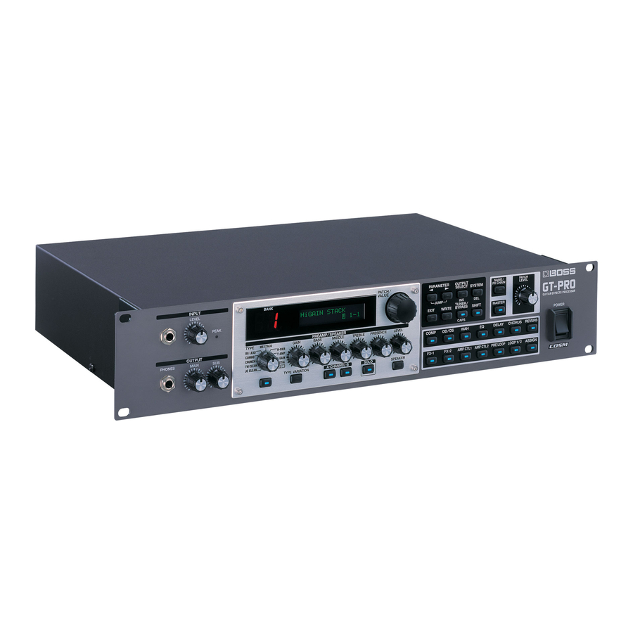
Thank you, and congratulations on your choice of the BOSS GT-PRO
Guitar Effects Processor.
Before using this unit, carefully read the sections entitled:
• IMPORTANT SAFETY INSTRUCTIONS (page 2)
• USING THE UNIT SAFELY (page 3–4)
• IMPORTANT NOTES (page 5–6)
These sections provide important information concerning the proper
operation of the unit.
Additionally, in order to feel assured that you have gained a good grasp of
every feature provided by your new unit, Owner's manual should be read in
its entirety. The manual should be saved and kept on hand as a convenient
reference.
■ Printing Conventions in This Manual
• Text or numerals enclosed in square brackets [ ] indicate bottons.
[WRITE]
[SYSTEM]
• EXP pedal is an abbreviation of "Expression pedal."
• Reference such as (p. **) indicate pages in this manual to which you can refer.
Copyright © 2005 BOSS CORPORATION
All rights reserved. No part of this publication may be reproduced in any form without the written
permission of BOSS CORPORATION.
WRITE button
SYSTEM button
Advertisement
Table of Contents

Related Manuals for Boss GT-PRO


Summary of Contents for Boss GT-PRO
- Page 1 Owner’s Manual Thank you, and congratulations on your choice of the BOSS GT-PRO Guitar Effects Processor. Before using this unit, carefully read the sections entitled: • IMPORTANT SAFETY INSTRUCTIONS (page 2) • USING THE UNIT SAFELY (page 3–4) • IMPORTANT NOTES (page 5–6) These sections provide important information concerning the proper operation of the unit.
-
Page 2: Important Safety Instructions
WARNING: To reduce the risk of fire or electric shock, do not expose this apparatus to rain or moisture. The lightning flash with arrowhead symbol, within an CAUTION equilateral triangle, is intended to alert the user to the RISK OF ELECTRIC SHOCK presence of uninsulated “dangerous voltage”... -
Page 3: Using The Unit Safely
• When using the unit with a rack or stand recom- • If smoke or unusual odor occurs mended by Roland, the rack or stand must be • Objects have fallen into, or liquid has been carefully placed so it is level and sure to remain spilled onto the unit;... - Page 4 • Before using the unit in a foreign country, consult entangled. Also, all cords and cables should be with your retailer, the nearest Roland Service placed so they are out of the reach of children. Center, or an authorized Roland distributor, as listed on the “Information”...
-
Page 5: Important Notes
• Although the LCD and LEDs are switched off when the restore the data, and Roland assumes no liability POWER switch is switched off, this does not mean that the concerning such loss of data. - Page 6 • Use only the specified expression pedal (EV-5; sold separately). By connecting any other expression pedals, you risk causing malfunction and/or damage to the unit. • Use a cable from Roland to make the connection. If using some other make of connection cable, please note the following precautions.
-
Page 7: Table Of Contents
Contents IMPORTANT SAFETY INSTRUCTIONS ..2 Chapter 4 Introduction to Effects and Parameters..28 USING THE UNIT SAFELY ......3 PREAMP/SPEAKER (Preamp/Speaker Simulator) ..28 OVERDRIVE/DISTORTION........... 31 IMPORTANT NOTES........ 5 DELAY ................32 Using the HOLD (Hold Delay) .......... 34 Main Features ........10 CHORUS................ - Page 8 Running the GT-PRO from a Computer ..... 91 on an External MIDI Device from the GT-PRO ... 78 About MIDI ..............79 How MIDI messages are transmitted and received..79 Main types of MIDI message used by the GT-PRO ..79 About the MIDI implementation ........80...
- Page 9 Adjusting the Display Contrast (LCD Contrast) ..96 Input/output device settings ........... 124 Switching the Software settings ..............125 Sounds Input to the GT-PRO (Input Select)....96 Adjusting the Tone of the Sounds Input Driver installation to the GT-PRO (Input Level/Input Presence) .....97 and settings (Macintosh) .....126...
-
Page 10: Main Features
Professional Guitar Effects System Everything that has gone into the GT-PRO, from the use of only the finest analog parts, to the quality AD/DA converter for superior wide dynamic range, to the balanced XLR and digital (coaxial) output connectors, is geared toward providing the absolute best in sound, offering the pro guitarist an effects processor of unprecedented quality that is worthy of the name “PRO.”... -
Page 11: Names Of Things And What They Do
This switches between preamp Channels A and B. 3. Display SOLO Button A variety of information about the GT-PRO appears This switches the Solo switch (p. 29) on and off. here. The left display shows the bank number. SPEAKER Button 4. - Page 12 8. WAH On/Off Button Use for making settings for the GT-PRO’s overall Press to change the settings. operating environment. The indicator lights when the GT-PRO is connected to 9. EQ On/Off Button your computer. Press to change the settings. 23. EXIT Button 10.
-
Page 13: Rear Panel
This disconnects the 1: GND pin from the input’s ground. Switch this to “ON” if humming or other noise 3. CTL 1/2 Jack from ground loops becomes a problem. The GT-PRO is Connect the optional foot switches (such as the FS-6/ normally used with this set to OFF. -
Page 14: Signal Flow
Names of Things and What They Do Signal Flow Control IN (MIDI) Control OUT (MIDI) GT-PRO IN (Audio) GT-PRO OUT (Audio) RETURN 2 SEND 2 RETURN 1 SEND 1 AMP CTL 2 AMP CTL 1 (from USB) RETURN SEND... -
Page 15: Chapter 1 Playing Sounds
Front Panel Digital Recorder etc. Stereo Headphones Tuner etc. Guitar Amp Foot Switch EXP Pedal EXP Pedal (FS-6 etc.) (Roland EV-5 etc.) (Roland EV-5 etc.) External Effects Processor External Effects Processor OUTPUT INPUT INPUT OUTPUT MIDI IN MIDI OUT OUTPUT... -
Page 16: Turning On The Power
• Are all external devices properly connected? * When using the unit with a foot switch (the optional FS-6) • Is the volume on the GT-PRO, your amp, and all other connected to the CTL 1/2 jack and CTL 3/4 jack, set the connected devices turned down to the minimum level? MODE switch and POLARITY switch as shown below. -
Page 17: Adjusting The Input Level
The Main Output Select settings screen appears. fig.01-0090d * If the input level is too high, the GT-PRO will not produce the desired effects. When using the GT-PRO with different guitars, you can conveniently adjust the input levels for each patch with 2. -
Page 18: Selecting The Sub Out Output Device (Amp) (Sub Output Select)
1. Before turning off the power, confirm the following. Select the type of device connected to the SUB OUT jack/ • Is the volume on the GT-PRO, your amp, and all other connector. connected devices turned down to the minimum level? fig.01-0081... -
Page 19: Creating Your Own Favorite Tones (Patches)
A “P” appears in the right display when a Preset patch is being used. fig.02-0030d * When the GT-PRO is set to FC-200 mode (p. 81), the banks are indicated by numbers one less than the normal numbers (User: 0–19; Preset: 20–39). -
Page 20: Adjusting The Tones With The Knobs
Turning the Effect On and Off The GT-PRO panel features eight knob controls. These knobs The GT-PRO’s internal effects are switched on and off with let you make adjustments or changes to the selected patch’s button controls. The indicator for an effect’s ON/OFF button tone quickly and easily. -
Page 21: Setting The Effects Simply (Quick Fx)
Chapter 2 Creating Your Own Favorite Tones (Patches) Setting the Effects Simply Calling Up Existing Patch Settings (QUICK FX) Just as with the Quick Settings, you can call up and use only the specific effect settings you need from the User and Preset Each effect includes prepared sample settings called “Quick patches. -
Page 22: Making More Precise Effect Settings
] (or [ ]). With items for which The selected effect is inserted at the cursor position. there aren’t that many parameters, the GT-PRO jumps to * Use [MASTER] to set the Noise Suppressor, use [ASSIGN] to the last (or first) parameter. -
Page 23: Naming Patches (Patch Name)
Chapter 2 Creating Your Own Favorite Tones (Patches) Naming Patches (Patch Name) Each patch can be given a name (Patch Name) consisting of up to sixteen characters. You’ll probably want to take advantage of this feature by assigning names that suggest the sound you’ll obtain, or the song in which it’ll be used. -
Page 24: Chapter 3 Saving The Tones You Have Created
* You can also use the procedure described in “How to Switch 4. Press [WRITE]. Patches (Patch Change)” (p. 19) to select the save destination. The GT-PRO switches to the copy-destination patch, and 3. Press [WRITE]. you’re returned to the Play screen. -
Page 25: Exchanging Patches (Patch Exchange)
You can return (initialize) the User patches to their original standard settings. On the GT-PRO, you can “swap” or exchange the positions This is convenient when you want to create a new patch from of two User patches. The following explains how this is done. -
Page 26: Initializing Patches With A Tone Similar To What You Have In Mind
In addition to the patches actually used in you like ahead of time as effects is a convenient way to create performances, the GT-PRO also offers a collection of sample new patches. settings that are a great help in creating new patches. -
Page 27: Copying The Preamp/Speaker Settings To Another Channel
Chapter 3 Saving the Tones You Have Created Copying the PREAMP/SPEAKER 4. When you want to change the User Quick Setting name (12 characters), use PARAMETER [ ] to Settings to Another Channel move the cursor, and use the PATCH/VALUE dial to change the characters. -
Page 28: Chapter 4 Introduction To Effects And Parameters
Chapter 4 Introduction to Effects and Parameters PREAMP/SPEAKER (Preamp/ In this chapter you will find detailed descriptions for each of the GT-PRO’s onboard effects, and the parameters used to Speaker Simulator) control them. COSM technology plays an indispensable role in simulating The sound being input to each effect is called the “direct... - Page 29 Chapter 4 Introduction to Effects and Parameters Parameter/ Parameter/ Explanation Explanation Range Range Dynamic Sens This turns off the speaker simulator. This is the built-in speaker of the amp you Effective with Dynamic selected for Chan- Original selected with “Type.” nel Mode.
- Page 30 Models the sound of the Channel 1 CLEAN JC CLEAN R-FIER Cln Mode on the MESA/Boogie DUAL Rectifi- JC-120 This is the sound of the Roland JC-120. Models the sound of the Channel 2 RAW Warm Clean This gives a mellow, clean sound. R-FIER Raw...
-
Page 31: Overdrive/Distortion
Chapter 4 Introduction to Effects and Parameters OVERDRIVE/DISTORTION Type List Type Explanation This effect distorts the sound to create long sustain. This is a booster that works very well with It provides 30 types of distortion and three different custom Booster COSM amps. -
Page 32: Delay
Chapter 4 Introduction to Effects and Parameters DELAY Parameter/ Explanation Range Hold This effect adds delayed sound to the direct sound, giving Up to 2.8 seconds of performance content is recorded, then played more body to the sound or creating special effects. back repeatedly. - Page 33 Chapter 4 Introduction to Effects and Parameters Parameter/ Explanation Range You can change the value in increments of ten by Delay1 HiCut (Delay 1 High Cut Filter) *1 pressing [SHIFT] so its indicator is lighted before you This sets the frequency at which the high cut rotate the PATCH/VALUE dial.
-
Page 34: Using The Hold (Hold Delay)
Chapter 4 Introduction to Effects and Parameters CHORUS Using the HOLD (Hold Delay) * Recording and playback of performances and other operations In this effect, a slightly detuned sound is added to the are carried out with pedals while Hold is in effect. Connect original sound to add depth and breadth. -
Page 35: Reverb
Chapter 4 Introduction to Effects and Parameters REVERB COMP (Compressor) This effect adds reverberation to the sound. This is an effect that produces a long sustain by evening out the volume level of the input signal. You can switch it to a Parameter/ “limiter”... -
Page 36: Wah
Chapter 4 Introduction to Effects and Parameters FX-1/FX-2 You can control the wah effect in real time by adjusting the With FX-1 and FX-2, you can select the effect to be used from EXP pedal connected to the EXP PEDAL 1 or 2 jack or FC-200 the following. -
Page 37: Acs (Advanced Compressor)
Chapter 4 Introduction to Effects and Parameters ACS (Advanced Compressor) LM (Limiter) This is an effect that produces a long sustain by evening out The limiter attenuates loud input levels to prevent distortion. the volume level of the input signal. You can also use it as a Parameter/ “limiter”... -
Page 38: Aw (Auto Wah)
Chapter 4 Introduction to Effects and Parameters TM (Tone Modify) Parameter/ Explanation Range This changes the tone of the connected guitar. Frequency Adjusts the center frequency of the Wah ef- Parameter/ 0–100 fect. Explanation Range Peak Type Adjusts the way in which the wah effect ap- see below Selects the type of tone modification. -
Page 39: Tr (Tremolo)
Chapter 4 Introduction to Effects and Parameters PH (Phaser) Parameter/ Explanation Range By adding varied-phase portions to the direct sound, the phaser effect gives a whooshing, swirling character to the Adjusts the tone for the low frequency -50–+50 sound. range. High Parameter/ Explanation... -
Page 40: Fl (Flanger)
Chapter 4 Introduction to Effects and Parameters FL (Flanger) The flanging effect gives a twisting, jet-airplane-like With the volume level of the left and right sides alternately character to the sound. changing, when playing sound in stereo, you can get an effect that makes the guitar sound appear to fly back and Parameter/ forth between the speakers. -
Page 41: Uv (Uni-V)
Chapter 4 Introduction to Effects and Parameters UV (Uni-V) SG (Slow Gear) Although this resembles a phaser effect, it also provides a This produces a volume-swell effect (“violin-like” sound). unique undulation that you can’t get with a regular phaser. Parameter/ Explanation Range Parameter/... -
Page 42: Str (Sitar Simulator)
Chapter 4 Introduction to Effects and Parameters STR (Sitar Simulator) FB (Feedbacker) This simulates the sound of the sitar. This allows you to use feedback playing techniques. * Note that the notes you want to apply feedback to must be Parameter/ played singly and cleanly. -
Page 43: Afb (Anti-Feedback)
Chapter 4 Introduction to Effects and Parameters AFB (Anti-feedback) Parameter/ Explanation Range This prevents the acoustic feedback that can be produced by * When set to BPM, the value of each parameter will be set according to the body resonances of a guitar. the value of the Master BPM (p. -
Page 44: Wsy (Wave Synth)
Chapter 4 Introduction to Effects and Parameters WSY (Wave Synth) SEQ (Sub Equalizer) This is a synth sound that processes the guitar input signal. This adjusts the tone as a sub equalizer. A parametric type is adopted for the high-middle and low-middle range. Parameter/ Explanation Range... -
Page 45: Fx-2
Chapter 4 Introduction to Effects and Parameters FX-2 Parameter/ Explanation Range Pre Delay *1 You can use the following effects in FX-2 in addition to whatever effect is shared by FX-1 and FX-2. Adjusts the time from when the direct 0 ms–300 ms, sound is heard until the harmonist sounds are heard. -
Page 46: Creating Harmonist Scales (User Scale)
Sets the note name of the input sound. You can also play -50–+50 Make fine adjustments to the pitch shift. individual notes on the guitar and let the GT-PRO The amount of the change in the Fine “100” is equivalent to that of interpret the note name. -
Page 47: Pb (Pedal Bend)
Chapter 4 Introduction to Effects and Parameters PB (Pedal Bend) RT (Rotary) This lets you use the pedal to get a pitch bend effect. This produces an effect like the sound of a rotary speaker. The EXP pedal automatically switches to the pedal bend Parameter/ function when PB is selected. -
Page 48: 2Ce (2 X 2 Chorus)
Chapter 4 Introduction to Effects and Parameters 2CE (2 x 2 Chorus) AR (Auto Riff) Two separate stereo chorus units are used for the low- This allows you to automatically produce a phrase simply by frequency and high-frequency ranges in order to create a picking a single note. -
Page 49: Creating Original Phrases (User Phrase)
Sets the note name of the input sound. You can also play tar sound, then send the square waveform ( ) from the inter- individual notes on the guitar and let the GT-PRO judge nal sound generator. the note name. -
Page 50: Ac (Acoustic Processor)
Chapter 4 Introduction to Effects and Parameters Parameter/ Parameter/ Explanation Explanation Range Range PWM Depth (Pulse Width Modulation Depth) *2 Synth Level 0–100 Adjusts the depth of the PWM. Adjusts the volume of the synthesizer 0–100 sound. When it is set to “0,” no PWM effect is obtained. Direct Level Cutoff Frequency 0–100... -
Page 51: Sh (Sound Hold)
Chapter 4 Introduction to Effects and Parameters SH (Sound Hold) EQ (Equalizer) You can have sound played on the guitar be held Adjusts the tonal quality. A parametric type equalizer is used continuously. This effect allows you to perform the melody for the upper and lower midrange. -
Page 52: Loop (External Effects Loop) 1/2
Use this when Stereo 1 you want to mix the GT-PRO’s effects sounds together with the Signals are output in stereo from the SEND 1/2 jacks and input in sound with the external effects device applied to it. -
Page 53: Pre Loop
Use this when you want to mix that use processes requiring detection of performance the GT-PRO’s effects sounds together with the sound with the exter- nal effects device applied to it. data may not function properly when PRE LOOP is... -
Page 54: Amp Ctl (Amp Control) 1/2
By connecting your guitar amp’s channel switching jack to The following parameters can be set with MASTER. the GT-PRO’s AMP CTL 1 (AMP CTL 2) jack, you can then • NS (Noise Suppressor) use [AMP CTL 1] ([AMP CTL 2]) to switch the amp channel. -
Page 55: Patch Level
By making use of the Assign settings (p. 66), things can • In Assign (p. 66), set “FV: Level” as the target and be set up so that a foot switch connected to the GT-PRO “EXP PEDAL 2” as the source. -
Page 56: Fx Chain (Effect Chain)
ASSIGN Set this when controlling multiple effects with the foot switch or expression pedal connected to the GT-PRO or via MIDI or other external data. For more detailed information, refer to “Setting External... -
Page 57: Creating Original Effects Types (Customize)
Chapter 5 Creating Original Effects Types (Customize) With the GT-PRO’s Customize function, you can rely on your Parameter/ own sensibilities and create a totally new effect by tweaking Explanation Range the settings for the “Preamp/Speaker Simulator,” Type “Overdrive/Distortion,” and “Pedal Wah.” The result can fig.05-0030d... -
Page 58: Customizing The Speakers
Chapter 5 Creating Original Effects Types (Customize) Parameter/ Explanation Parameter/ Range Explanation Range Preamp High Speaker Size fig.05-0090d fig.05-0120d Adjusts the preamp section’s high-frequen- -50–+50 5”–15” Selects the size of speaker. cy tone. Color Low fig.05-0130d Customizing the Speakers You can make two different sets of settings, Custom 1 and Custom 2. -
Page 59: Customizing Overdrive/Distortion
Chapter 5 Creating Original Effects Types (Customize) Customizing Parameter/ Overdrive/Distortion Explanation Range Type You can make three different sets of settings, Custom 1, fig.05-0190d Custom 2, and Custom 3. * The sound of any patch that uses Custom 1, 2, or 3 will be altered if the custom settings are edited. -
Page 60: Customizing Pedal Wah
Chapter 5 Creating Original Effects Types (Customize) Customizing Pedal Wah Parameter/ Explanation Range You can make three different sets of settings, Custom 1, Type Custom 2, and Custom 3. fig.05-0260d The sound of any patch that uses Custom 1, 2, or 3 will be altered if the custom settings are edited. -
Page 61: Chapter 6 Using Pedals To Control The Effects
You can assign and control the parameters you want to external MIDI device. external pedals (expression pedals, foot switches) connected to the GT-PRO and to external MIDI devices (such as the FC- 200). “Setting the FV (Foot Volume) Operation for Individual On top of all this, the GT-PRO features an “Internal Pedal... -
Page 62: Setting The Operation Of The External Foot Switch (Ctl 1, 2, 3, 4 Function)
CTL 1 * The following shows the correspondence between the foot switch and CTL function when two foot switches are connected using a special connection cable (Roland PCS-31: sold separately). fig.06-0020 3. Use the PATCH/VALUE dial to select the external foot switch function. -
Page 63: Setting The Operation Of The External Exp Pedal (Exp1, 2 Function)
EXP PEDAL 1 and EXP PEDAL 2 Master BPM (TAP) Used for tap input of the Master BPM. jacks as global settings for the entire GT-PRO. Delay Time (TAP) Used for tap input of the delay time. -
Page 64: Setting The Operation For An External Midi Device (Cc#7, Cc#80, Cc#1 Function)
These settings are applied to the entire GT-PRO, controlling Auto Pedal Bend (p. 47) is switched on, the CC#7 the GT-PRO by means of Control Change messages from an then automatically functions as a “pedal FC-200 or other external MIDI device connected to the GT- wah”... -
Page 65: Setting The Fv (Foot Volume) Operation For Individual Patches (Exp1/Cc#7 Foot Volume)
Chapter 6 Using Pedals to Control the Effects Setting the FV (Foot Volume) Operation for Value Explanation Controls the Start/Stop of external MIDI de- Individual Patches (EXP1/CC#7 Foot Volume) MIDI Start/Stop vices (such as sequencers). Controls the Play/Stop of external MIDI de- MMC Play/Stop vices (such as hard disk recorders). -
Page 66: Setting External Controller Functions To Individual Patches (Assign)
Quick ASSIGN Current Setting external pedals (foot switches or expression pedals) - - -: User Setting connected to the GT-PRO, and the control of parameters by Quick ASSIGN User Quick Setting (p. 26) means of Control Change messages from external MIDI U**: devices (such as the FC-200). -
Page 67: Manual Settings
Chapter 6 Using Pedals to Control the Effects Manual Settings 5. Rotate the PATCH/VALUE dial to change the setting’s value. Here, you can individually determine which controller is to 6. Repeat Steps 4 and 5 as needed. control which parameter. fig.06-0130 7. - Page 68 The value of the parameter selected as the target changes within the range defined by “Min” and “Max,” as set on the When controlling the On/Off target with the GT-PRO. EXP pedal: When using an external foot switch, or other controller that fig.06-0190...
- Page 69 Chapter 6 Using Pedals to Control the Effects Source Source Mode fig.06-0200d fig.06-210d This sets the controller (source) that affects the target This determines whether the control pedal will function as a parameter. momentary type switch (such as the optional FS-5U). Controllers that can be selected as the source are shown Value Explanation...
-
Page 70: Internal Pedal System
Internal Pedal System This is activated when the EXP pedal connected to the EXP PEDAL 1 jack is depressed. The GT-PRO features a function called Internal Pedal system. CTL PEDAL 1 This function assigns specified parameters to a virtual EXP... - Page 71 Chapter 6 Using Pedals to Control the Effects Parameter/ Explanation Range You may be unable to change parameter settings when Curve the following functions are set for the target while fig.06-0270d INTERNAL PEDAL or WAVE PEDAL is selected for the source.
-
Page 72: Using The Gt-Pro With External Midi Devices Connected
Outputting Program Change Messages is being played. The patches are switched automatically When a patch is selected on the GT-PRO, a Program Change when the program numbers corresponding to the patches are message corresponding to the patch number is transmitted input along with the performance data at the points where simultaneously. -
Page 73: Notes Regarding The Midi Messages That Can Be Transmitted And Received
Chapter 7 Using the GT-PRO with External MIDI Devices Connected Notes Regarding the MIDI Messages That Making the Settings for MIDI Functions Can Be Transmitted and Received Here is a description of the GT-PRO’s MIDI functions. Set The MIDI messages that the GT-PRO can transmit and them as needed, depending on the intended use. - Page 74 When set to “Off, “Control Change messages are not output. are switched. * On the GT-PRO, Bank Select messages are output simultaneously with Program Change messages. For more details, reefer to p. 77. MIDI EXP1 OUT (MIDI EXP 1 Pedal Out) fig.07-0100d...
-
Page 75: Transmitting And Receiving Midi Data
Chapter 7 Using the GT-PRO with External MIDI Devices Connected Transmitting and Receiving When Transmitting Data to Another GT-PRO Connect as shown in the figure below, and match the Device MIDI Data ID for the transmitting and receiving devices. fig.07-0160... -
Page 76: Receiving Data
At this stage, even more data can be received. * When data that can be received by the GT-PRO is not included, “Waiting...” immediately appears in the display. 4. Press [EXIT] to quit Bulk Load. -
Page 77: Setting The Program Change Map
When switching patches using Program Change messages transmitted by an external MIDI device, you can freely set the correspondence between Program Change messages received by the GT-PRO and the patches to be switched to in the “Program Change Map.” Initial Program Change Map Settings The program Change map set at the factory is shown below. -
Page 78: Enabling/Disabling The Program Change Map Settings (Midi Map Select)
External MIDI Device from the GT-PRO This setting determines whether patches are switched When a patch is selected on the GT-PRO, the bank select and according to the Program Change Map settings, or to the program change messages sent from the GT-PRO correspond default settings. -
Page 79: About Midi
Chapter 7 Using the GT-PRO with External MIDI Devices Connected About MIDI MIDI has sixteen channels 1–16, and MIDI messages will be received by the instrument (the receiving device) whose channel matches the channel of the transmitter. MIDI is an acronym for Musical Instrument Digital Interface,... -
Page 80: About The Midi Implementation
Chapter 7 Using the GT-PRO with External MIDI Devices Connected About the MIDI implementation MIDI allows a variety of messages to be exchanged between instruments, but it is not necessarily the case that all types of message can be exchanged between any two MIDI devices. -
Page 81: Using The Gt-Pro Connected To The Fc-200
Switches FC-200 Mode on. Matching the FC-200’s display, GT-PRO Banks 0–39 are indicated. Start by making the FC-200-related settings on the GT-PRO. * Once FC-200 mode is switched on, data describing the GT-PRO’s own fig.08-0010 operations, as well as data describing the usage of an expression pedal or foot switch connected to the external pedal jack (MIDI PC OUT, MIDI EXP1 OUT, etc.;... -
Page 82: Setting The Timing For Switching Patches (Fc-200 Program Change Out)
GT-PRO to the FC-200 Parameter/ This procedure transmits the settings made in “Setting the Explanation Range Functions Related to the FC-200” (p. 81) from the GT-PRO to FC-200 PC Out the FC-200. fig.08-0060d Connecting To transmit the settings, connect the GT-PRO’s MIDI OUT Sets the timing for switching patches that connector to the FC-200’s MIDI IN connector as shown in the... -
Page 83: Transmitting Settings Data To The Fc-200
FC-200 2. Press [WRITE] to transmit the data. * Set the GT-PRO and FC-200 to the same MIDI channel. Both “Now sending...” is displayed, and the data is the GT-PRO and FC-200 are set at the factory to MIDI transmitted to the FC-200. -
Page 84: Using The Fc-200'S Ctl And Exp Pedals
* “FC-200 CTL” functions the same as “MIDI CC#80,” and “FC-200 EXP” functions the same as “MIDI CC#7.” Information describing the actions of the FC-200’s CTL and EXP pedals is transmitted to the GT-PRO in the form of MIDI “Setting External Controller Functions to Individual Patches messages (Control Changes). -
Page 85: Switching The Effect On And Off With The Fc-200'S Pedals (Manual Mode)
Selecting the Effect to Be Switched On and Off With the Pedals the FC-200’s Pedals (Manual Mode) The GT-PRO features a Manual mode, in which the pedals on 1. When you press PARAMETER [ ] while the FC-200 are used for switching specified effects on and off. -
Page 86: Advanced Settings
MIDI cables. • You can set the FC-200 from the GT-PRO without having to reconnect any MIDI cables. • When you turn on the power to the GT-PRO, the FC-200 is programmed with the corresponding settings for the GT-PRO. -
Page 87: Automatically Setting The Fc-200 With The Corresponding Gt-Pro Settings When Turning On The Gt-Pro
MIDI device as well as the GT-PRO, enabling You can have the FC-200 automatically programmed with you to control both the GT-PRO and the other external MIDI the corresponding GT-PRO settings by first switching the device with the FC-200. -
Page 88: Using The Gt-Pro Connected To A Computer Via Usb
* If the driver for the set mode has not yet been installed, at this a computer. You can save the tone settings (patches) you point you need to turn off the power to the GT-PRO and install the driver. -
Page 89: Setting Usb-Related Functions
Chapter 9 Using the GT-PRO Connected to a Computer Via USB Setting USB-Related Functions Parameter/ Explanation Range USB Mix Channel This section describes the GT-PRO’s USB functions. Set these functions according to how you want to use the unit. fig.09-0080d... -
Page 90: Recording The Gt-Pro's Output With A Computer
OUT jacks. Select” is displayed. fig.09-0140d The effect sound is output. Set this to On when using the GT-PRO as a standalone device, without connecting to a computer (no sound will be output if this is set to Off). Set this to Off if transmitting audio data internally through a com- 3. -
Page 91: Running The Gt-Pro From A Computer
Chapter 9 Using the GT-PRO Connected to a Computer Via USB Running the GT-PRO from a Computer You can use USB MIDI to run the GT-PRO from your computer. When you set the GT-PRO to the Advanced driver mode (p. -
Page 92: Chapter 10 Other Features
As the guitar volume changes during the performance, Dynamic Sens is adjusted in response to the volume The GT-PRO includes a function to control effect parameters when the preamps are switched. with the guitar dynamics as the instrument is played. This is not limited to touch wah, but provides tonal changes in real 5. -
Page 93: Using The Guitar Volume To Change Selected Effect Parameters (Assign Source)
] (or [ ]). With items for which parameters to be controlled with the guitar volume, in the there aren’t that many parameters, the GT-PRO jumps to same manner as the parameters are changed with an the last (or first) parameter. -
Page 94: Adjusting The Overall Sound To Match The Usage Environment (Global)
Usage Environment (Global) Mid Freq (Middle Frequency) fig.10-0140d The GT-PRO includes a feature that allows you to change the overall tone temporarily. This is called the “Global function.” With the Global function, you can temporarily change your settings to match those of your equipment and the operating... -
Page 95: Sub Global Eq
Chapter 10 Other Features Sub Global EQ USB/Digital Out This adjusts the tone of the SUB OUT regardless of the Parameter/ equalizer on/off settings of individual patches. Explanation Range USB/DGT Out Ch. (USB/Digital Out Channel) Parameter/ Explanation Range fig.09-0060d Sub Low EQ fig.10-0180d MAIN, SUB, Selects the signals output from the USB and... -
Page 96: Adjusting The Display Contrast (Lcd Contrast)
Switching the Sounds Input Contrast (LCD Contrast) to the GT-PRO (Input Select) Depending on where the GT-PRO is placed, the display (on This selects the input sounds, those input through the INPUT the right) may become difficult to read. If this occurs, adjust jacks or those input via USB, to which the effects are applied. -
Page 97: Adjusting The Tone Of The Sounds Input To The Gt-Pro (Input Level/Input Presence)
Keeping Effect Sounds Playing After Patches the GT-PRO (Input Level/Input Presence) Are Switched (Patch Change Mode) The GT-PRO includes a function used for adjusting the tone The GT-PRO features a mode that is enabled when spatial to match the connected guitar. -
Page 98: Using The Identical Preamp Settings In All Patches (Preamp Mode)
Limiting the Patches That Can Be in All Patches (Preamp Mode) Switched (Patch Extent) With the GT-PRO, you can have a preamp be set globally for By setting an upper limit to the patches, thus limiting the use in all patches. -
Page 99: Changing The Exp Pedal Mode When Patches Are Switched (Assign Hold)
If the expression pedal is operated, and that information is transmitted to the GT-PRO, the volume will change in accord with the pedal’s movement. 3. Press [EXIT] to return to the Play screen. -
Page 100: Switching The Output/Input Level
Chapter 10 Other Features Switching the Output/Input Level Checking the Effect Level with the Level Meter You can switch between the MAIN OUT, SUB OUT, and LOOP 1/2 SEND output levels and the LOOP 1/2 RETURN You can meter the output level of each effect. This is handy input levels. -
Page 101: Tuning The Guitar (Tuner/Bypass)
How to Tune 1. Play a single open note on the string being tuned. When the Tuner is turned on, sounds input to the GT-PRO The name of the note closest to the pitch of the string that are output directly as is (bypassed), and the tuner is was played appears in the display. - Page 102 Mute Sounds are muted, and no sound is output. Bypass Sounds input to the GT-PRO bypass the processing and are output directly as is. When the tuner is switched on while set to “Bypass,” you can adjust the volume of the direct sound by moving the EXP pedal (EXP pedal connected to the EXP PEDAL 1 jack or the FC-200’s EXP pedal (MIDI...
-
Page 103: Appendices
Restoring the Factory List of Factory Settings Settings (Factory Reset) Parameter Value TUNER Restoring the GT-PRO to the settings made at the factory is TUNER Pitch A= 440Hz referred to as “Factory Reset.” Bypass TUNER Out Not only can you return all of the settings to the values in... - Page 104 Appendices Parameter Value Monitor Cmd Disable Dir Monitor Driver Mode Advanced MIDI RX Channel Omni Mode Omni On TX Channel Device ID Sync Clock Auto PC OUT EXP 1 OUT CC#7 CTL1 OUT CC#81 CTL2 OUT CC#80 CTL3 OUT CTL4 OUT MIDI Map Select Manual Mode Pedal 1...
-
Page 105: Midi Implementation Chart
MIDI has been implemented on this unit. If you should require this publication (such as when you intend to carry out byte-level programming), please contact the nearest Roland Service Center or authorized Roland distributor. Mode 1 : OMNI ON, POLY... -
Page 106: Specifications
Appendices Specifications Controls < Front Panel > INPUT LEVEL knob GT-PRO: Guitar Effects Processor MAIN OUTPUT knob SUB OUTPUT knob AD Conversion (PREAMP/SPEAKER) 24 bit + AF method TYPE knob DA Conversion GAIN knob 24 bit BASS knob MIDDLE knob... - Page 107 MIDI connectors IN/OUT/THRU to change without prior notice. AF Method (Adaptive Focus method) This is a proprietary method from BOSS & Roland that vastly improves the signal-to-noise (S/N) ratio of the A/ D and D/A converters.
-
Page 108: Gt-Pro Software System Requirements
Microsoft® Windows® XP Professional/XP Home Edition/ 2000 Professional/Me/98SE/98 While under most conditions, a computer similar to the CPU/Clock: above will permit normal operation of the GT-PRO, Pentium®, Celeron™, Intel-compatible Processor/600 MHz BOSS cannot guarantee compatibility solely on these or Higher factors. -
Page 109: Installing & Setup The Usb Driver
The USB Driver is software which passes data between the GT-PRO and the application (sequencer software etc.) that is running on the USB-connected computer. The GT-PRO Driver sends data from the application to the GT-PRO, and passes data from the GT-PRO to the application. -
Page 110: Driver Installation And Settings (Windows)
You can use the native driver included on the GT-PRO Driver CD-ROM to record, play, and edit audio with high quality and stable timing. In Special driver mode, audio signals are transferred between the GT-PRO and the computer at a bit depth of 24 bits and a sample rate of 44.1 kHz. -
Page 111: Installing The Special Driver
The SetupInf dialog box will appear. You are now ready to install the driver. Before connecting the USB cable, switch the GT-PRO’s driver mode to “Advanced.” For instructions on switching the GT-PRO’s driver modes, refer to “Switching the Driver Mode” (p. 88). - Page 112 Driver installation and settings (Windows) With the power switch turned OFF, use the USB cable to connect the GT-PRO to your computer. Make sure that the GT-PRO’s OUTPUT MAIN and SUB knobs are set to the lowest setting, then switch ON the POWER switch.
- Page 113 Driver installation and settings (Windows) If you changed the “Driver Signing Options” setting (p. 111, step 4), restore the setting to its previous state after restarting Windows. Log on to Windows using the same user account as the one used when the driver was installed.
-
Page 114: Windows 2000 Users
For instructions on switching the GT-PRO’s driver modes, refer to “Switching the Driver Mode” (p. 88). With the power switch turned OFF, use the USB cable to connect the GT-PRO to your computer. Make sure that the GT-PRO’s OUTPUT MAIN and SUB knobs are set to the lowest setting,... - Page 115 Driver installation and settings (Windows) If the “File signature verification” (Step 4) setting was not set to “Ignore”, a “Digital Signature Not Found” dialog box will appear. If “File signature verification” is set to “Warn” Click [Yes]. Continue the installation. If “File signature verification”...
- Page 116 Driver installation and settings (Windows) Giving priority to background services In Windows 2000, make settings to enable background processing. If you fail to make this setting, you may experience interruptions in the sound. To ensure that MIDI and audio processing occurs smoothly, use the following procedure to make settings. Click the Windows Start button, and from the menu that appears, select Settings | Control Panel.
-
Page 117: Windows Me/98 Users
For instructions on switching the GT-PRO’s driver modes, refer to “Switching the Driver Mode” (p. 88). With the power switch turned OFF, use the USB cable to connect the GT-PRO to your computer. Make sure that the GT-PRO’s OUTPUT MAIN and SUB knobs are set to the lowest setting, then switch ON the POWER switch. -
Page 118: Installing The Os-Standard Driver
For instructions on switching the GT-PRO’s driver modes, refer to “Switching the Driver Mode” (p. 88). With the power switch turned OFF, use the USB cable to connect the GT-PRO to your computer. Make sure that the GT-PRO’s OUTPUT MAIN and SUB knobs are set to the lowest setting, then switch ON the POWER switch. -
Page 119: Windows Me Users
For instructions on switching the GT-PRO’s driver modes, refer to “Switching the Driver Mode” (p. 88). With the power switch turned OFF, use the USB cable to connect the GT-PRO to your computer. Make sure that the GT-PRO’s OUTPUT MAIN and SUB knobs are set to the lowest setting, then switch ON the POWER switch. -
Page 120: Windows 98 Users
Insert the Windows CD-ROM into the CD-ROM drive of your computer, and the power switch turned OFF, then use the USB cable to connect the GT-PRO to your computer. Make sure that the GT-PRO’s OUTPUT MAIN and SUB knobs are set to the lowest setting, then switch ON the POWER switch. - Page 121 Driver installation and settings (Windows) Check CD-ROM drive, and click [Next]. A dialog box like the one shown below will appear. fig.12-0094 Click [Next]. File (driver) copying will begin. If the Windows CD-ROM is not inserted in the CD-ROM drive, a Insert Disk dialog box may appear.
- Page 122 Driver installation and settings (Windows) Click [Next], and proceed with the installation in the same way as in steps 8–10. When installation of the USB audio device driver is complete, a dialog box like the one shown here will appear. fig.12-0098 Click [Finish].
-
Page 123: Driver Settings
* For details on how to make settings for your software, you should also refer to the owner’s manual for your software. * If you are unable to select the GT-PRO in the device settings of your software, it is possible that the GT-PRO driver was not installed correctly. -
Page 124: Input/Output Device Settings
Driver installation and settings (Windows) Input/output device settings If you will be using the Windows Media Player application with the GT-PRO, specify the input/output devices as follows. Depending on your system, the The method in which you make device settings will depend on the software you are using. For System icon may be displayed details, refer to the owner’s manual for your software. -
Page 125: Software Settings
This concludes the procedure for setting the input and output destinations. Software settings Before you start up your software, use a USB cable to connect the GT-PRO to your computer. If your software allows you to specify audio input/output settings, choose BOSS GT-PRO. -
Page 126: Driver Installation And Settings (Macintosh)
You can use the native driver included on the GT-PRO Driver CD-ROM to record, play, and edit audio with high quality and stable timing. In Special driver mode, audio signals are transferred between the GT-PRO and the computer at a bit depth of 24 bits and a sample rate of 44.1 kHz. -
Page 127: Installing The Special Driver
Insert the CD-ROM into the CD-ROM drive of your computer. In the Driver (Mac OS X) folder of the CD-ROM, double-click GTPROUSBDriver.pkg. The display will indicate “Welcome to the BOSS GT-PRO USB Driver Installer”. The message “This Installer package Click [Continue]. -
Page 128: Driver Settings
• Close your software before you unplug the GT-PRO’s USB cable. • Turn off the Sleep setting of your Macintosh. • The GT-PRO will not work in the Classic environment of Mac OS X. Use it when the Classic environment is not running. -
Page 129: Mac Os 9 Users
Disconnect the GT-PRO from the Macintosh before you perform the installation. If a GT-PRO is already connected to your Macintosh when you install the driver, a message like the following will appear when the Macintosh is started up. Perform the steps described below as appropriate for the message that is displayed. - Page 130 For instructions on switching the GT-PRO’s driver modes, refer to “Switching the Driver Mode” (p. 88). With the power switch turned OFF, use the USB cable to connect the GT-PRO to your computer. Make sure that the GT-PRO’s OUTPUT MAIN and SUB knobs are set to the lowest setting, then switch ON the POWER switch.
- Page 131 BOSS GT-PRO, and click [OK]. fig.12-0260 * If the dialog box does not show “BOSS GT-PRO,” check whether the GT-PRO is connected correctly, and start up OMS Setup once again. Verify that the OMS MIDI Device Setup dialog box lists the GT-PRO. Then click all check boxes from the BOSS GT-PRO to check them, and click [OK].
- Page 132 Driver installation and settings (Macintosh) From the Edit menu, select OMS MIDI Setup. In the OMS MIDI Setup dialog box that appears, check Run MIDI in background, and click [OK]. fig.12-0290 Exit OMS Setup. Make MIDI device settings on your sequencer software. For details on settings, refer to the manual that came with your software.
- Page 133 Driver in MIDI Configuration, and click [OK]. fig.12-0320 * If the dialog box does not show “GT-PRO Driver,” check whether the GT-PRO is connected correctly, and start up FreeMIDI Setup once again. The About Quick Setup dialog box will appear.
- Page 134 Driver installation and settings (Macintosh) Click [Continue]. In the dialog box that appears, set Studio Location: to GT-PRO,GT-PRO Port, and click [>>Add>>]. fig.12-0340 When settings are complete, click [Done]. A setting window will appear. In the setting window, change the device name indicating the MIDI device connected to the GT-PRO as follows.
- Page 135 Be sure to install the MIDI driver before you install the ASIO driver. In/Out Interface) This is an audio interface standard This section explains how to install the ASIO driver that allows the GT-PRO to be used by your promoted by the Steinberg sequencer software or audio editing software.
-
Page 136: Installing The Os-Standard Driver
Now, return the GT-PRO’s OUTPUT MAIN/SUB knob to the original position, then try Once set this way, all sounds clicking on an alert in the list. If the sound of the alert comes from the GT-PRO when you do from your Macintosh (including so, it means that the GT-PRO is being recognized and that the driver has been installed properly. - Page 137 • Disconnect the USB cable from the GT-PRO only after you have quit your sequencer or other software. • Leave the Sleep function of your Macintosh turned off. • The GT-PRO will not work in the Classic environment of Mac OS X. Use the GT-PRO when the Classic environment is not running.
-
Page 138: Mac Os 9 Users
For instructions on switching the GT-PRO’s driver modes, refer to “Switching the Driver Mode” (p. 88). With the power switch turned OFF, use the USB cable to connect the GT-PRO to your computer. Make sure that the GT-PRO’s OUTPUT MAIN and SUB knobs are set to the lowest setting, then switch ON the POWER switch. - Page 139 With the volume turned down on the GT-PRO and on your peripheral audio equipment, click [Start Test]. Test signals will be output from the GT-PRO; left first, then right, as indicated in the screen. fig.12-450 In the Sound dialog box, click the Input tab.
- Page 140 In Choose a source for sound input (Device), select USB audio. fig.12-0460 If USB audio is not displayed, close the Sound dialog box, and disconnect the GT-PRO’s USB cable from the Macintosh. Perform the driver installation (p. 138) once again.
-
Page 141: Setting The Special Driver's Functions
Setting the Special Driver’s Functions Adjusting the audio latency When using the GT-PRO in Advanced mode, you can change the driver settings to adjust the latency of the audio. To adjust the latency, change the Buffer Size in the driver settings dialog box. - Page 142 Open the Control Panel and double-click BOSS GT-PRO. The BOSS GT-PRO Driver Settings dialog box will appear. * In Windows XP, click “Switch to classic view” to switch the display to the classic view. BOSS GT-PRO will not be displayed unless the classic view is selected.
-
Page 143: Troubleshooting
→ When Output Channel (p. 95) is set to “PATCH,” the output destination set with Master Output (p. 55) is ● The memory backup battery inside the GT-PRO has run used. down. (This message will appear when the power is ❏... -
Page 144: Other Problems
❏ Is the SYS: Input Select (p. 96) set to “USB In?” → On the GT-PRO, patches can be selected only when the → When set to “USB In,” audio signals may, depending on Play screen is displayed. Press [EXIT] to return to the the software settings, end up looping. -
Page 145: Problems Related To The Usb Driver
MIDI Messages That Can Be Transmitted and Received” The “System Properties” dialog box will appear. (p. 73). → When the GT-PRO is connected to a computer via USB, 2. Click the “Device Manager” tab. MIDI messages arriving at the MIDI IN connector cannot 3. - Page 146 Did you make “Driver Signing Options”? → In order to install/re-install the driver, you must make If you find BOSS GT-PRO with a yellow “!” or a red “?” displayed beside it, delete this in the same way. “Driver Signing Options.”...
-
Page 147: Problems When Using The Usb Driver
Was the driver installed correctly? are connected to a computer, noise may occur depending → In order for you to play back audio data via the GT-PRO, on your system. In such cases, connect only the GT-PRO the driver must be installed. For installation and settings, to your computer. - Page 148 ❏ Is the SYS: Input Select (p. 96) set to “USB In?” → When SYS: Input Select is set to “USB In,” the GT-PRO’s → Try using the following procedure to change your disk effects are applied to the audio signals from the computer.
- Page 149 • Depending on the way in which you connect to the ❏ On some computers, audio playback may be Internet, use the GT-PRO with the following settings. interrupted due to the Power Management settings in If you connect to the Internet via a LAN cable the Control Panel.
- Page 150 (p. 5) ❏ Was a heavy processing load experienced while using the GT-PRO, such as accessing the CD-ROM drive or a network? → If an operation involving a heavy processing load is performed while the GT-PRO is in use, it may not operate correctly.
-
Page 151: Deleting The Special Driver
[Restart]. Your computer will then restart. Mac OS 9 users 1. Disconnect the USB cable (by which the GT-PRO is connected) from your Macintosh. 2. From the system extensions folder, drag “USB GT-PRO Driver” into the trash to delete it. -
Page 152: Patch List
Patch List ■ User Patch Patch Name OD/DS Type PRE Ch.Mode Ch.A Type Ch.B Type U 1- 1 STACK DRIVE Single (Ch.A) MS HiGain Power Stack U 1- 2 HEAVY METAL DRV Single (Ch.A) R-FIER Vnt1 R-FIER Mdn1 U 1- 3 MS1959 LEAD Single (Ch.A) MS1959(I) - Page 153 Patch List Patch Name OD/DS Type PRE Ch.Mode Ch.A Type Ch.B Type U 6- 1 AMERICAN DS Single (Ch.A) MS1959(I) MS HiGain U 6- 2 HEAVY STACK Single (Ch.A) Power Stack Metal Stack U 6- 3 BLUES+MS1959 MIX Dual Mono Blues MS1959(II) U 6- 4...
- Page 154 Patch List Patch Name OD/DS Type PRE Ch.Mode Ch.A Type Ch.B Type U11- 1 DEEP STACK LEAD Single (Ch.A) MS HiGain MS HiGain U11- 2 BIG LEAD T-Scream Single (Ch.A) StackCrunch JC-120 U11- 3 LONG SUSTAIN DRV Fat OD Single (Ch.A) SLDN StackCrunch U11- 4...
- Page 155 Patch List Patch Name OD/DS Type PRE Ch.Mode Ch.A Type Ch.B Type U16- 1 60’s CLEAN Single (Ch.A) VO Clean VO Drive U16- 2 FAT CLEAN Single (Ch.A) Warm Clean JC-120 U16- 3 BIG HALL CLEAN Single (Ch.A) JC-120 Warm Clean U16- 4 LOW TONE JAZZ Single (Ch.A)
-
Page 156: Preset Patch
Patch List ■ Preset Patch Patch Name OD/DS Type PRE Ch.Mode Ch.A Type Ch.B Type P21- 1 STACK DRIVE Single (Ch.A) MS HiGain Power Stack P21- 2 HEAVY METAL DRV Single (Ch.A) R-FIER Vnt1 R-FIER Mdn1 P21- 3 MS1959 LEAD Single (Ch.A) MS1959(I) MS HiGain... - Page 157 Patch List Patch Name OD/DS Type PRE Ch.Mode Ch.A Type Ch.B Type P26- 1 AMERICAN DS Single (Ch.A) MS1959(I) MS HiGain P26- 2 HEAVY STACK Single (Ch.A) Power Stack Metal Stack P26- 3 BLUES+MS1959 MIX Dual Mono Blues MS1959(II) P26- 4 SMOOTH DETUNE Single (Ch.A) SmoothDrive...
- Page 158 Patch List Patch Name OD/DS Type PRE Ch.Mode Ch.A Type Ch.B Type P31- 1 DEEP STACK LEAD Single (Ch.A) MS HiGain MS HiGain P31- 2 BIG LEAD T-Scream Single (Ch.A) StackCrunch JC-120 P31- 3 LONG SUSTAIN DRV Fat OD Single (Ch.A) SLDN StackCrunch P31- 4...
- Page 159 Patch List Patch Name OD/DS Type PRE Ch.Mode Ch.A Type Ch.B Type P36- 1 60’s CLEAN Single (Ch.A) VO Clean VO Drive P36- 2 FAT CLEAN Single (Ch.A) Warm Clean JC-120 P36- 3 BIG HALL CLEAN Single (Ch.A) JC-120 Warm Clean P36- 4 LOW TONE JAZZ Single (Ch.A)
-
Page 160: Index
Index Numerics 2 x 2 Chorus ................48 DEL ................23, 27, 56 2CE ..................... 48 DELAY ................12, 32–33 DGT ................... 22 DIGITAL OUT ................. 13 Digital Signature ..............115 AC ....................50 Direct Monitor ................89 Acoustic Processor ..............50 DIRECT OUT ................ - Page 161 Index GS ....................38 MIDI IN ..................13 GT-PRO Editor ................. 88 MIDI Map Select ..............78 GT-PRO Librarian ..............88 MIDI OUT ................. 13 Guitar Amp ................ 18, 54 MIDI Sequencer ..............75–76 Guitar In ................90, 96 MIDI THRU ................13 Guitar Simulator ..............
- Page 162 Index Preamp/Speaker Simulator ........... 28 PRESENCE ................. 11, 20 Target ..................67 Preset Bank ................19 Target Range ................68 Preset Patch ................19 TM ....................38 Program Change ..............72, 79 Tone Modify ................38 Program Change Map ............. 77 Total NS ..................
- Page 163 Cet appareil numérique de la classe B respecte toutes les exigences du Règlement sur le matériel brouilleur du Canada. For the USA DECLARATION OF CONFORMITY Compliance Information Statement Model Name : GT-PRO Type of Equipment : Guitar Effects Processor Responsible Party : Roland Corporation U.S. Address : 5100 S.Eastern Avenue, Los Angeles, CA 90040-2938 (323) 890-3700 Telephone :...
- Page 164 For EU Countries 03899334 07-09-3N...
Need help?
Do you have a question about the GT-PRO and is the answer not in the manual?
Questions and answers