Advertisement
Overview
UT210E mini digital clamp meter features high reliability, safety, precision and compact design. Its resolution ratio is 1mA. Maximum range has maximum range of 100A AC/DC; particular VFC start mode. Entering this mode can accurately measure voltage and current which has VFC frequency conversion. Voltage or current response display is bue valid value. Whole range overload protection, reliable measurement accuracy and unique appearance design makes it an outstanding new generation functional electrician/ electric power measurement instrument.
Open case inspection
Open the package and take out the instrument. Please check whether the following accessories are missing or damaged. If any item missing or damaged, please contact your supplier immediately.
| 1 copy |
| 2 pieces |
| 1 copy |
| 1 pair |
Electrical symbol
 | Low battery |  | Warning |  | Buzzing on-off |
 | ACV/DCV |  | Diode |  | Earthing |
 | ACA/DCA |  | Double insulation | ||
 | Danger! High voltage | ||||
 | Application around and removal from UNINSULATED HAZARDOUS LIVE conductors is permitted | ||||
General standard
- Maximum faulty operation protection voltage between input terminal and earthing is 600V.
- Maximum overload protection for clamp head terminal: 100A.
- Maximum display: 2000Counts, update 2~3 times per second.
Over range displays "OL".
Diode: approx. 3.2V
Range: automatic (exclusive of electricity gear)
Polarity: automatic
Work temperature: 0°C~40°C
Relative humidity: 0°C~30°C:75%, 30°C~40°C:50%
Storage temperature: -10°C~50°C - Electromagnetic compatibility: In IV/m radio frequency field: overall frequency=designated precision+5%, radio frequency field above IV/m has no designated index.
- Work altitude: 0~2000m
- Built-in battery: AAA 1.5Vx2 pieces
- Low battery: LCD displays "
![]() "
" - Dimensions: approx. approx. (175x60x33.5)mm, maximum clamp head size is 17 mm.
- Weight: approx. 170g (including battery)
 "
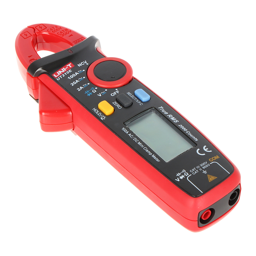
"Product panel figure

See Fig. 1
- Clamp head.
- Protective barrier.
- Clamp head trigger: pull the trigger to open clamp head.
- NCV indicator: when the induced AC electric field intensity and induction distance satisfy designated value, it will send out warning sound and flashes.
- Function selection button: rotate this button to switch to corresponding functions indicated on the panel.
- HOLD/backlight key: for measuring readings/long press 2s to turn on or turn off backlight.
- ZERO key: used for DCA zero, capacitance/voltage measurement relative value.
- SELECT key: select function mode, such as ACV/DCV, resistance/on-off/diode/capacitance, ACA/DCA, etc. in AC voltage and current gear, long press this key for more than 2s to enter or exit VFC function.
- LCD display screen: measurement function, symbol and numerical value.
- Positive terminal input jack: when measure voltage, resistance/onoff/capacitance/diode, red meter pen inserts into this jack.
- Input jack at COM terminal: when measure voltage, resistance/on-off/capacitance/diode, black meter pen inserts into this jack.
- Indication mark for geometric center of the clamp head.
LCD full view figure

See Fig. 2
| No. | Symbols | Instructions |
| 1 | TRMS | True valid value measurement status prompt |
| 2 | AC/DC | AC/DC voltage measurement prompt |
| 3 |  | Negative reading |
| 4 |  | Diode measurement prompt |
| 5 |  | Circuit on-off measurement prompt |
| 6 |  | Data hold prompt |
| 7 | Ω kΩ MΩ | Resistance unit: Ω, kΩ, MΩ |
| 8 | Hz kHz MHz | Frequency unit: Hz, kHz, MHz |
| 9 | mV, V | Voltage unit: mV, V |
| 10 | mA, A | Current unit: mA, A |
| 11 | nF μF mF | Capacitance unit: nF, μF, mF |
| 12 | (EF) NCV | Noncontact AC voltage induction prompt |
| 13 | Auto | Auto range prompt |
| 14 | ZERO/REL | Zero/relative measurement prompt |
| 15 | VFC | Variable frequency voltage/current measurement prompt |
| 16 |  | Low built-in battery prompt |
| 17 |  | Auto power-off prompt |
Operation instructions
AC/DC voltage measurement
- Select AC voltage or DC voltage gear
- Insert red meter pen into red jack (positive terminal), black meter pen into black jack (COM terminal)
- Touch the test piece by red and black meter pen, for example, power socket (Figure 3).

- Read measurement value from LCD screen.


When measure voltage, maximum input voltageis 600V(AC/DC), do not exceed this limitation, otherwise it may cause electric shock or damage to the meter.
Resistance/circuit on-off/diode/capacitance
- Insert red meter pen into red jack (positive terminal), black meter pen into black jack (COM terminal)
- Connect meter pen in parallel to test piece for measurement (Figure 4)

- Read measurement value from LCD screen.

When measure resistance/on-off/capacitance/diode range, do not input vdtage over DC 60V or AC 30V to avoid injury to human.
AC/DC current measurement
- AC
- Select AC range (2A~, 20A~, 100A~)
- Open clamp head, hook electric wire (single wire), place electric wire on geometric center indicated by clamp head, make sure the left and right clamp heads are totally closed. There is no gap between the left and right clamp heads (Figure 5).

- Read measurement data from LCD.
- DC
- Press SELECT key to enter DC range (2A
![]() , 20A
, 20A ![]() , 100A
, 100A ![]() )
) - Press ZERO key before measurement to make readings zero. If it does not return to zero after one press, then press it several times until the reading is zero. Note: as the product is highly sensitive, to ensure correct measurement data, direction of meter during measurement should be the same as when it is in zero as much as possible (Figure 6).

- Open clamp head, hook electric wire (single wire), place electric wire on geometric center indicated by clamp head, make sure the left and right clamp heads are totally closed. There is no gap between the left and right clamp heads.
- Read measurement data from LCD. When the reading is positive, it means current flows from positive end indicated by clamp head to the negative end. Negative reading is the opposite.
- Press SELECT key to enter DC range (2A

 , 20A
, 20A 
When measure current, unplug test pen to avoid electric shock.
NCV noncontact electric field measurement
If you want to measure whether there is AC voltage or electromagnetic field, place front end of clamp head 8~15mm close to the test piece, analog quantity of inductive AC voltage is about ⩽ critical voltage 100V, display "EF", > critical voltage 100V, display "-", it has four "----" levels based on voltage size with different buzzing at each level, with NCV light flashing to discriminate electric field intensity. (Figure 7)

When ranges switch NCV measurement, please unplug the test pen to avoid electric shock
Other functions
- Long press HOLD key for 2s to tum on or turn off LCD backlight function.
- Automatic power-off: when measuring, if the rotary button has not pulled out in 15 minutes, the instrument will automatically power off to save energy. In automatic power-off mode, turn rotary button to OFF and restart the machine, or click any key to wake the instrument.
- Turn off automatic power-off function: press and hold SELECT key, then power-on start, you will heard 5 buzzing which means automatic power-off function is cancelled. Turn off and restart the machine, automatic power-off function will be recovered.
- The buzzer will send out 5 warnings 1 minute before automatic power off. A long buzz will be heard before power off. When automatic power-off function is canceled, you will hear 5 continuous warnings in every 15 minutes.
- Buzzer: press any key or rotate function switch, if such function key is valid, buzzer will "beep" once (lasting approx. 0.25s). In gear, when the circuit-under-test is conductive ( ⩽ 10 Ω ), buzzer makes sound continuously. When measure voltage or current outrange, buzzer will "Beep" to warn outrange, function status is as below:
- When AC, DC voltage > 600V, buzzer beeps
- 100A AC and DC gear: current > maximum range, buzzer beeps
- Low-voltage detect: when battery voltage is lower than 2.5V, battery under-voltage symbol
![]() appears, measurement accuracy may be lower once this symbol shows, replace battery timely; if it is lower than 2.2V, only battery under-voltage symbol shows after starting up, it can't work.
appears, measurement accuracy may be lower once this symbol shows, replace battery timely; if it is lower than 2.2V, only battery under-voltage symbol shows after starting up, it can't work. - When battery supply voltage lowers to 2.6V, LCD backlight will be in weak or non-start state; but measurement functions still work.
 appears, measurement accuracy may be lower once this symbol shows, replace battery timely; if it is lower than 2.2V, only battery under-voltage symbol shows after starting up, it can't work.
 Technical index
Accuracy: ±(a% reading + b word count), warranty period is 1 year.
Environment temperature: 23°C±5°C(73.4°F±9°F) relative humidity: 75%
DC voltage measurement
| Range | Resolution | Accuracy |
| 200.0mV | 0.1mV | ± (0.7%+5) |
| 2.000V | 1mV | ± (0.7%+3) |
| 20.00V | 10mV | |
| 200.0V | 100mV | |
| 600V | 1V |
Input resistance is about 10MΩ. (as input resistance is high, when 200mV range open circuit, there may be instable digital display, but measurement can be stabilized once the measured source with internal resistance lower than 10MΩ is connected, but the impact of intemal resistance of measured source on measurement reading should be considered)
Maximum input voltage: ±600V
AC voltage measurement
| Range | Resolution | Accuracy |
| 2.000V | 1 mV | ± (1.0%+3) |
| 20.00V | 10mv | |
| 200.0V | 100mV | ± (1.0%+3) V.F.C. mode: ± (4.0%+3) |
| 600V | 1V | ± (1.2%+3) V.F.C. mode: ± (4.0%+3) |
Input resistance: 10 MΩ in average.
Maximum input voltage: 600Vrms
- Show true virtual value. Frequency response: 45~400Hz
- Accuracy guarantee range: 5~100% range, short circuit allows < 10 residue readings.
- Non-sinusoidal wave counts add error by crest factor:
When crest factor is 1~2: Add 3%.
When crest factor is 2~2.5: Add 5%.
When crest factor is 2.5~3: Add 7%.
Resistance measurement
| Range | Resolution | Accuracy |
| 200.0Ω* | 0.1Ω | ± (1.0%+2) |
| 2.000kΩ | 1Ω | |
| 20.00kΩ | 10Ω | |
| 200.0kΩ | 100Ω | |
| 2.000MΩ | 1kΩ | ± (1.2%+3) |
| 20.00MΩ | 10kΩ |
Range: measured value=measurement display value-meter pen short circuit value
Open-circuit voltage is about IV
Overload protection: 600V-RMS
Circuit on-off and diode measurement
 circuit on-off, circuit on-off,  diode measurement diode measurement | ||
| Range | Resolution | Remarks |
| 0.1Ω | Resistance value for circuit disconnect: ⩾ 150Ω, buzzer makes no sound; Resistance value for circuit conduct: ⩽ 10Ω, buzzer beeps continuously. |
| 1 mV | Open circuit voltage is 3.2V: normal voltage for silicon PN junction is 0.5Ё0.8V. |
Overload protection: 600V-RMS
Capacitance measurement
| Range | Resolution | Accuracy |
| 2nF | 1pF | ± (4%+10) |
| 20.00nF~200.0μF | 10pF~100nF | ±(4%+5) |
| 2.000mF~20.00mF | 1μF~10μF | ±10% |
Overload protection: 600V-RMS
⩽ 1 μF measured capacitance, it is suggested to use ZERO measurement mode to ensure accuracy.
DCA measurement
| Range | Resolution | Accuracy |
| 2.000A | 1 mA | ± (2%+8) |
| 20.00A | 10mA | ± (2%+3) |
| 100.0A | 100mA | ± (2%+3) |
Overload protection 100A
As external electromagnetic field such as the earth exists, to ensure accuracy of measurement reading, press ZERO key before measurement to make readings be zero. If it is not zero after one press, press it for several times until reading is zero. Direction of meter during measurement should be the same as when it is in zero as much as possible.
ACA measurement
| Range | Resolution | Accuracy |
| 2.000A | 1mA | ± (3%+10) V.F.C mode: (4.0%+10) |
| 20.00A | 10mA | ± (2.5%+8) V.F.C mode: ± (4.0%+10) |
| 100.0A | 100mA | ± (2.50/0+5) V.F.C mode: ± (4.0%+10) |
Overload protection 100A
- Accuracy warranty coverage: 5~100% range, 2A open circuit allows <20 residue readings.
- Displays are true valid value. Frequency response: 50~60Hz.
- Non-sinusoidal wave counts add error by crest factor:
- When crest factor is 1~2: Add 3%.
- When crest factor is 2~2.5: Add 5%.
- When crest factor is 2.5~3: Add 7%.
Maintenance and repair

before remove rear cover of the instrument, make sure power supply is off; meter pen leaves input port and circuitunder-test.
General maintenance and repair
* For maintenance and repair, use wet cloth and mild cleaner to clean instrument cover, do not use grinding agent Or solvent. If the instrument is abnormal, stop use it and maintain. If it is necessary to verify or maintain the instrument, maintain it by qualified professional serviceman or designated maintenance department.
Replace battery
* When LCD displays under-voltage  prompt, replace built-in battery immediately otherwise it will affect measurement accuracy.
* Battery specification: AAA 1.5V x2cells
Operation procedure:
- Place power switch on "off" position and remove meter pen from input jack
- Unscrew the screw fixed on the rear cover of battery by screwdriver, remove battery rear cover and take out old battery as shown in the figure 8.

- Replace 2 pcs of new batteries (specification AAA1.5V)

This instruction manual is subject to change without further notice.
Safety precautions
This Meter complies with EN 61010-1 Pollution Degree 2, measurement category: (CAT II 600V, CAT Ill 300V) and Double Insulation standards.
Conforms to UL STD. 61010-1, 61010-2-032, 61010-2-033 Certified to CSA STD. C22.2 NO. 61010-1,IEC STD 61010-2-032, 61010-2-033
CAT II: Applicable to test and measuring circuits connected directly to utilization points (socket outlets and similar points) of the lowvoltage MAINS installation.
CAT Ill: Applicable to test and measuring circuits connected to the distribution part of the building's low-voltage MAINS installation, before use and follow all safety instructions.
- Use the clamp meter by following operation instructions, otherwise safety functions of the current clamp meter may fail to protect you.
![shock hazard]() Abide by national safety laws and regulations. When operate in dangerous and live wire exposed environment, use personal protection equipment to prevent accidents such as electric shock and arc discharge.
Abide by national safety laws and regulations. When operate in dangerous and live wire exposed environment, use personal protection equipment to prevent accidents such as electric shock and arc discharge. - Do not cross any position other than protective barrier of current clamp meter.
- Before each use, check whether current clamp meter housing or output cable insulation cracks or damaged first, also check for poor connected parts. Especially pay attention to insulating layer around the clamping mouth.
- Before removing the battery cover, please remove clamp meter from all energized circuit and disconnect lead wire.
- Do not use clamp meter in circuit with voltage higher than 600V this or frequency higher than 400Hz.
- Measurement category class is CAT II 600V/CAT Ill 300V, pollution degree is 2. Do not use it out of scope.
![shock hazard]() Be cautious when work in environment with exposed wire. Contact with wire may result in electric shock.
Be cautious when work in environment with exposed wire. Contact with wire may result in electric shock. ![shock hazard]() For voltage above 60V DC (direct current), 30V AC (AC effective value) or 42V AC (peak value), such voltage may cause electric shock.
For voltage above 60V DC (direct current), 30V AC (AC effective value) or 42V AC (peak value), such voltage may cause electric shock.- Probe assemblies used for MAINS measurements CAT II 600V/CAT Ill 300V according to IEC 61010-031, If you want to replace the probe assemblies and they need the same level CAT II 600V/CAT Ill 300V or better level. Protection impairment if used in a manner not specified by the manufacturer.
- Function switches shall be set at the correct position prior to measurement. It is forbidden to perform gear conversion in measurement to guard against damage to the meter.
Manufacturer:
Uni-Trend Technology (China) Limited
No 6, Gong Ye Bei 1st Road
Songshan Lake National High-Tech Industrial
Development Zone, Dongguan City
Guangdong Province
China
Postal Code: 523 808
Headquarters:
Uni-Trend Group Limited
Rm901, 9/F, Nanyang Plaza
57 Hung To Road
Kwun Tong
Kowloon, Hong Kong
Tel: (852) 2950 9168
Fax: (852) 2950 9303
Email: info@uni-trend.com
http://www.uni-trend.com
Documents / Resources
References
Download manual
Here you can download full pdf version of manual, it may contain additional safety instructions, warranty information, FCC rules, etc.
Advertisement


Need help?
Do you have a question about the UT210E and is the answer not in the manual?
Questions and answers