Table of Contents
Advertisement
Quick Links
Advertisement
Table of Contents

Related Manuals for UNI-T UT255C


Summary of Contents for UNI-T UT255C
-
Page 2: Table Of Contents
Contents Safety Information ........................1 Introduction ........................1 Electrical Symbols ......................3 III. Technical Specifications ..................... 3 IV. Structure ..........................5 LCD Display ........................5 Display screen ...................... 5 Symbols description ....................6 Illustrations ......................... 7 VI. Operating Instructions ......................7 Operate the detector .................... -
Page 3: Safety Information
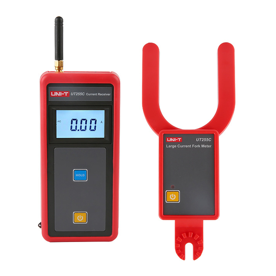
The UT255C is equipped with several useful features, such as data holding and storage. Additionally, the adjustable connector at the hot stick and U-shaped clamp jaws make it easy to clamp the measured conductor. -
Page 4: Electrical Symbols
Clamp jaws Wireless Model Range Resolution size structure distance UT255C 0.00A~9999A 0.01A Φ 68 mm Fork shaped 100 M II. Electrical Symbols Extremely dangerous! The operator must follow the safety information strictly, otherwise it may present a risk of electric shock, which can cause personal injury or death. -
Page 5: Structure
Conductor Measure bare conductor with voltage below 60KV (operate with fully- voltage extended hot stick) In testing mode, press HOLD to hold data (with the symbol “HOLD” Data hold displayed), press again to disable data hold. The symbol “MR” appears when entering data viewing mode. User can Data viewing cycle through the stored data. -
Page 6: Lcd Display
1. U-shaped clamp jaws 7. HOLD button 2. Detector 8. LCD display 3. Power indicator light 9. Receiver 4. Power button 10. Antenna 5. Adjustable connector 11. Retractable hot stick 6. Power button 12. Adjustable connector V. LCD Display 1) Display screen 5 / 11... -
Page 7: Symbols Description
(1). Alternating current symbol (6). Unit symbol (2). Low battery symbol (7). Data hold symbol (3). Data storage symbol (8). Decimal point (4). Data viewing symbol (9). 4-digit digital displa (5). 2-digit group No. of stored data 2) Symbols description (1). -
Page 8: Operating Instructions
(8). “no - -” is displayed dynamically to indicate no signal is received. VI. Operating Instructions Please carefully check before use if any component of the detector/receiver is damaged, do not use if any damage is found. Install battery according to the instructions in the user manual. 1. - Page 9 Conductor Conductor Push forward Conductor Pull back Figure C Figure B Figure A Grounding 10Kv/400V transformer Grounding Grounding Low - voltage current tes�ng High- voltage current tes�ng Caution! For your safety, please remove the detector from measured conductor after test. 3) Testing area The measured conductor shall be near the center of the bottom of the clamp jaws (Area A).
-
Page 10: Data Transfer
4) Data transfer The detector has wireless data transfer function. When the detector is in testing mode, the testing results are transferred to the receiver in wireless manner, then the receiver displays the testing results in real time and clearly. The detector transmits signal only in testing mode. -
Page 11: Data Hold
The receiver enters data reception mode when it is powered on. If the receiver receives transmission data, it will display testing data in real time; if not, it will keep searching signal and display the symbol “no - -”. The receiver shows the symbol “OL” to indicate the measured current is over the specified upper range. -
Page 12: Packing List
3. Press the button “ ” to check if the receiver/detector can power on normally, if not, please repeat Step 2 above. Ba�ery cover Ba�ery cover Loosen Tighten VIII. Packing List Detector 1 pc Receiver 1 pc Wireless antenna 1 pc Retractable hot stick 1 pc Carrying box...
Need help?
Do you have a question about the UT255C and is the answer not in the manual?
Questions and answers