Advertisement
Quick Links
—
ABB Servo Product
E530-PT Servo Drive
Quick installation guide
ABB Motion E-catalog
About this document
©2024 ABB All rights reserved.
This guide describes the mechanical and electrical installation of E530-PT servo
drive. For more information, refer to the E530-PT servo system user manual
(3AXD50000942800 [EN]).
1. Safety instructions
This section contains the safety instructions which you must obey during
installation, operation and maintenance on the drive. Read these instructions
carefully before any operation. If you ignore them, injury, death or damage can
occur.
For more safety information, refer to chapter
Safety
user manual.
These warning symbols are used:
Electricity warning tells you about hazards from electricity
which can cause injury or death, or damage to the equipment.
General warning tells you about conditions, other than those
caused by electricity, which can cause injury or death, or dam-
age to the equipment.
Electrostatic sensitive devices warning tells you about the
risk of electrostatic discharge which can cause damage to the
equipment.
Hot surface warning tells you about the burn hazard from the
high-temperature surface of the radiator.
Remaining time indicates the remaining time for capacitor
discharge. Make sure to wait for 5 minutes, after
disconnecting the power supply. Otherwise, there is a risk of
5 min
electric shock.
Motor machinery damage warning tells you about the risk of
motor damage, caused by harmful behaviour like knocking.
Refer to the user manual tells you to read the user manual
and quick installation guide manual before operating the
device.
Grounding tells you the protective grounding (PE). Make sure
the system is properly grounded.
1.1 Unpacking
Please check whether the drive type matches the product you ordered.
Make sure the specifications (rated power) of the servo drive and
motor are correctly matched. Ignoring this instruction could result in
personal injury or death or equipment damage.
1.2 Installation safety instructions
Warning! Do not connect the input power to the servo drive during
installation.
• Keep the servo drive in its package until you install it. After unpacking,
protect the drive from dust, debris and moisture.
• Use required personal protective equipment: safety shoes with metal toe
caps, goggles, protective gloves and long sleeves, etc, as some parts have
sharp edges.
• Avoid locating the servo drive in the environment of high temperature,
humidity, corrosive gas, flammable and explosive gas, metal dust, oil mist,
water vapor, etc.
• Avoid locating the servo drive in a place with constant vibration or physical
shock, strong electromagnetic interference, or sudden temperature change.
• Do not attach the drive by riveting or welding.
• Vacuum clean the area around the servo drive before the start-up to prevent
the drive cooling fan from drawing dust inside the drive..
• Ensure that debris from drilling and grinding does not enter the drive when
installing. Electrically conductive debris inside the unit may cause damage or
malfunction.
• The installation surface is as close to vertical as possible and strong enough
to support the servo drive. It is recommended to use a metal installation
surface. The material below the installation is not flammable.
• Ensure sufficient cooling or have adequate devices to dissipate the heat.
• Make sure all system components are mounted are properly grounded and
the connecting surfaces left unpainted.
1.3 Wiring safety instructions
Warning! Wiring to the drive must be done by a qualified electrical
engineer. Ignoring the following safety instructions may cause personal
injury or death and equipment damage.
Note! Electrical design and installation must comply with local laws and
regulations. ABB is not responsible for installations that violate local
laws or regulations.
• After disconnecting the input power, always wait for 5 minutes to let the
intermediate circuit capacitors discharge before wiring or any inspection.
• Avoid touching any other live parts in the workplace. Take special
precautions when working near exposed conductors.
• Make sure that the servo system is properly grounded in accordance with
local regulations to ensure the reliability of the equipment.
• Do not connect the servo drive to a voltage higher than that marked on the
model label. Do not connect the drive to a voltage higher than that marked
on the type designation label. It can cause damage to the drive.
• Do not solder the exposed wires. Solder will shrink over time, potentially
causing loose connections. Use crimp connections whenever possible.
• The AC power supply must be fused.
• The control cable should have sufficient electrical safety distance from the
main circuit cable, or double or reinforced insulation isolation measures
should be provided between the control cable and main circuit cable.
• Lock out and tag out after disconnecting from the power. Make sure that re-
connection is not possible.
1.4 Grounding safety instructions
Warning! Obey these instructions. If you ignore them, injury or death, or
equipment malfunction can occur, and electromagnetic interference
can increase. If you are not a qualified electrical professional, do not do
grounding work.
•
Always ground the drive, the motor and adjoining equipment. This is
necessary for the personnel safety.
•
Make sure that the conductivity of the protective earth (PE) conductors is
sufficient. Obey the applicable national and local regulations.
•
When using shielded cables, make a 360° grounding of the cable shields at
the cable entries to reduce electromagnetic emission and interference.
•
In a multiple-drive installation, connect each drive separately to the
protective earth (PE) busbar of the power supply.
Note:
•
Power cable shields are suitable for equipment grounding conductors only
when adequately sized to meet safety regulations.
3AXD50000942787
•
According to standard IEC/EN 61800-5-1(4.4.4.3.3), because the normal
Rev C EN 2024-06-15
touch current of the drive is more than 3.5 mA AC or 10 mA DC, a fixed
connection must be uesed and:
- a protective earth conductor with a minimum cross-sectional area of 10
2
mm
Cu or 16 mm
- a second protective earth conductor of the same cross-sectional area as
the original protective earth conductor, or
- a device that automatically disconnects the supply if the protective earth
conductor is damaged.
•
Leakage current >3.5 mA AC.
1.5 Operation safety instructions
Warning! Before operation, adjust the drive parameters to match the
mechanical system parameters. Mismatched parameters may cause
damage to the servo drive, motor or mechanical system.
• Before you adjust the drive operation limits (speed, current, etc.) , make sure
that the motor and all driven equipment can operate throughout the set
operation limits.
• Beware of hot surfaces. The surfaces of drive system components (such as a
in E530-PT servo system
mains choke or braking resistor, if present) become hot when the system is
in use, and remain hot for a while after disconnection of the electrical supply.
A brake resistor can generate enough heat to ignite combustible materials.
To avoid fire hazard, keep all combustible materials and flammable vapors
away from brake resistors.
• Make sure that the safety circuits (eg. emergency stop) connected to the
servo drive are validated.
• The maximum number of drive power-ups is five in ten minutes. Too frequent
power-ups can damage the charging circuit of the DC capacitors.
• Before you activate the fault reset or restart functions of the drive control
program, make sure that there is no dangerous situations can occur. Make
sure that the reset parameter is correct and the safety measures are taken.
Do not reset the fault with command input.
• If the drive continues operation automatically after reset or restart, the
installation must be clearly marked as defined in IEC/EN/UL 61800-5-1,
subclause 6.5.3, for example, "THIS MACHINE STARTS AUTOMATICALLY".
1.6 Maintenance safety instructions
Warning! Only qualified electricians are allowed to maintain the drive.
Do not touch any internal or external parts of the servo drive and motor,
unnecessarily. Otherwise, there is a risk of getting electric shock.
• If the internal fan (or other component) fails, contact your local ABB
representative or Authorized Service Center.
• The drive is not field repairable. Never attempt to repair a malfunctioning
drive, contact your local ABB representative or Authorized Service Center.
2. Product overview
2.1 Drive components
The figure shows the drive package with its contents.
Make sure that all of the items are present and that there
are no signs of damage.
No.
1
Servo drive
Quick installation guide (ZH + EN)
2
2.2 Drive labels
The drive has two labels:
•
Model information label in front of the drive
•
Type designation label on the left side of the drive.
7
8
9
1
Drive type
2
Manufacturer information
3
Degree of protection
4
Nominal ratings
5
Valid markings
2
Al , or
Description
2 2
1
E530-PT0S-1KW0-1
ABB Beijing Drive Systems Co.,Ltd.
2
No.1, Block D, A-10 Jiuxianqiao Beilu,
Chaoyang District, Beijing, P.R. China
Forced air cooling
Icc
3
IP20 Open type
HW
Input
Output
4
U1 1P 200~240VAC
U2 3P 0~U1
I1 1P 10.0 A
I2 5.35 A
f1 50/60Hz
f2 0~250Hz
Pn 1.00 kW
5
6
10
S/N W222312345
Made in China
6
QR code (serial number)
7
Drive type
8
Serial number
9
QR code (ABB servo web site)
10
S/N: Serial number of format
MYYWWXXXXX, where
M: Manufacturer designation
YY: Year of manufacture: 22, 23, 24,
...for year 2022, 2023, 2024...
WW: Week of manufacture: 01,02,03,
...for week 1, week 2, week 3...
XXXXX: Running number that starts
each week.
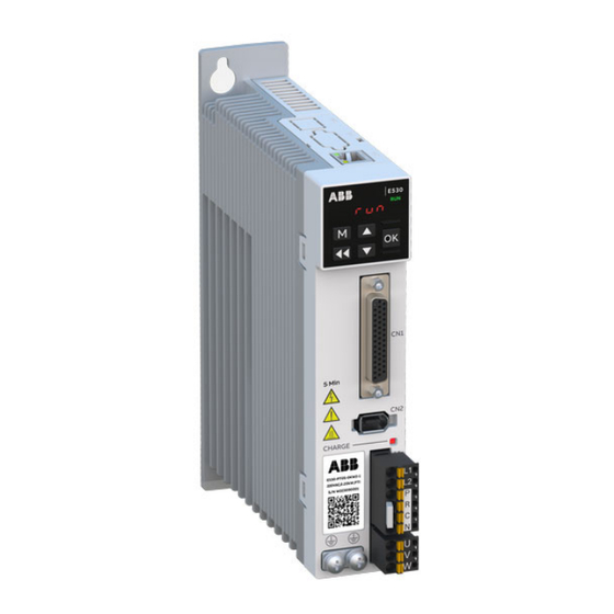
2.3 Drive interface
F2, F3
1
2
3
4
5
6
8
10
7
9
No.
F2,F3
Modbus TCP communication and
1
PC tool connector (RJ45,CN4)
Five digits 7-segment display
2
Control keys
3
Control connector (CN1)
4
Encoder connector (CN2)
5
6
Input power and brake resistor
terminals
7
Motor power terminals
8
Type designation label
9
Grounding screws
10
Short-circuit connector
Note: For frames sizes F2 and F3, L1 and L2 can connect to either neutral wire or
live wire.
Definition of drive port voltage level:
Drive port
CN1/CN2/CN4
L1/L2/L3/P/C/R/U/V/W
2.4 System structure
Frame sizes F2 and F3
220V AC power
Fuse
Breaker
Filter
1 Power cable, 1-phase
2 Motor cable
3 Encoder cable (1394 connector)
Frame size F4
220V AC power
Fuse
Breaker
Filter
1 1
1 Power cable, 1-phase or 3-phase
2 Motor cables
3 Encoder cable (1394 connector)
2.5 Technical data
5 kA
Ratings
A
Input rating
Frame
Type
size
E530-PT0S-0KW2-1
F2
E530-PT0S-0KW4-1
F2
E530-PT0S-0KW8-1
F3
E530-PT0S-1KW0-1
F3
E530-PT0S-1KW5-2
F4
E530-PT0S-2KW0-2
F4
Fuses
Input current
Frame
Drive type
size
E530-PT0S-0KW2-1
F2
E530-PT0S-0KW4-1
F2
E530-PT0S-0KW8-1
F3
E530-PT0S-1KW0-1
F3
E530-PT0S-1KW5-2
F4
E530-PT0S-2KW0-2
F4
For detailed information on cables, connectors, breakers, brake resistors,
filters, ferrite ring and fans, refer to section
system user manual.
F4
1
2
3
4
5
6
10
9
7
8
F4
Modbus TCP communication and
PC tool connector (RJ45,CN4)
Five digits 7-segment display
Control keys
Control connector(CN1)
Encoder connector (CN2)
Input power, motor power and
brake resistor terminals
Type designation label
Grounding screws
Short-circuit connector
Baffle
DVC level
DVC As
DVC C
PC
(Servo Composer)
PLC/controller
Control cable
4
(44-pin D-type connector)
5 Communication cable (RJ45)
6 Grounding busbar
PC
(Servo Composer)
PLC/controller
Control cable
4
(44-pin D-type connector)
5 Communication cable (RJ45)
6 Grounding busbar
Output rating
I
I
I
P
1N
2N
2max
N
A
A
A
kW
2.5
1.50
4.50
0.20
4.7
2.90
8.70
0.40
8.5
5.00
15.00
0.75
10.0
5.35
16.05
1.00
6.4
7.60
22.80
1.50
8.0
11.00
33.00
2.00
Icc
Bussmann
RMS
type
A
kA
2.5
5
C10G10
4.7
5
C10G10
8.5
5
C10G20
10.0
5
C10G20
6.4
5
C10G25
8.0
5
C10G25
3.6 Accessories
in E530-PT Servo
Advertisement

Related Manuals for ABB E530-PT


Summary of Contents for ABB E530-PT
- Page 1 This guide describes the mechanical and electrical installation of E530-PT servo 1.5 Operation safety instructions drive. For more information, refer to the E530-PT servo system user manual (3AXD50000942800 [EN]). Warning! Before operation, adjust the drive parameters to match the mechanical system parameters.
- Page 2 1°C Front view Back view Side view 1.5kW/2kW: 1-phase or 3-phase 220V input, with embedded Air pressure 86 kPa ~ 106 kPa, contact ABB if out of range Tightening Hole distance Screw Dimensions braking resistor and with fan torque...
Need help?
Do you have a question about the E530-PT and is the answer not in the manual?
Questions and answers