Sign In
Upload
Manuals
Brands
ABB Manuals
Servo Drives
E530-PT
ABB E530-PT Manuals
Manuals and User Guides for ABB E530-PT. We have
2
ABB E530-PT manuals available for free PDF download: User Manual, Quick Installation Manual
ABB E530-PT User Manual (416 pages)
Servo system
Brand:
ABB
| Category:
Servo Drives
| Size: 17 MB
Table of Contents
Table of Contents
5
Safety Instructions
11
Contents of this Chapter
11
Use of Warnings and Notes
11
General Safety in Installation, Start-Up and Maintenance
12
Electrical Safety in Installation, Start-Up and Maintenance
14
Precautions before Electrical Work
14
Additional Instructions and Notes
16
Grounding
16
General Safety in Operation
17
Introduction to the Manual
19
Contents of this Chapter
19
Applicability
19
Target Readers
19
Categorization by Frame Size
19
Contents of this Manual
20
List of Related Manuals
21
Quick Installation and Start-Up Flowchart
22
Terms and Abbreviations
23
Product Information
25
Contents of this Chapter
25
Product Overview
25
Scope of Delivery
26
Drive
26
Motor
29
System Combination Table
32
Interface Introduction
33
Drive Interface
33
Motor Interface
34
Accessories
36
Cable
36
Communication Cable
40
Connector
41
Fuse
42
Circuit Breaker
42
Brake Resistor
42
EMC Filter
43
Ferrite Ring
43
Fan
43
Technical Data
43
Technical Data of Servo Drive
44
General Technical Data
44
Technical Data of Servo Motor
48
Technical Data of Cables
53
CE Marking
54
Compliance with en 61800-3
54
Compliance with the European Low Voltage Directive
55
Compliance with the European EMC Directive
55
Compliance with the European Rohs Directive
55
Materials
56
Function List
58
Control Mode Overview
58
Control Functions Overview
58
Declaration of Conformity
59
Disclaimers
59
Generic Disclaimer
59
Cybersecurity Disclaimer
59
Installation
61
Contents of this Chapter
61
Preparation before Installation
61
Unpacking
61
Required Tools
62
Installation Precautions
62
Installing the Servo Drive
64
Installation Direction
64
Installation Space
64
Installation Steps
68
Dimensions and Mounting Holes
69
Installing the Servo Motor
72
Unpacking
72
Motor Pin Definition
72
Precautions for Motor Installation
75
Motor Installation Steps
78
Installation Dimensions
80
Wiring
85
Contents of this Chapter
85
System Structure
86
Frame Size F2 and F3
86
Frame Size F 4
87
Selecting the Cables
88
Cable Routing
88
Grounding
88
Main Circuit Wiring
89
AC Input - L1/L2/L3
90
Motor Output - U/V/W
94
Motor Cable Information
96
Brake Resistor - P/R/C
102
Selecting the Brake Resistor
105
Common DC Bus Wiring - P/N
107
Encoder Wiring
109
Control Signal Wiring
114
Control Signal Interface
114
Pulse Inputs
119
Digital Inputs
122
Digital Outputs
125
Analog Inputs
127
Encoder Frequency Dividing Pulse Output
128
Motor Brake Control Output
129
Modbus TCP/IP Wiring
130
Typical Application Wiring
131
PTI Control Mode
131
FP Control Mode
133
Speed Control Mode
136
Torque Control Mode
138
PLC Wiring Example
140
Analog Input Signals Wiring between AC500-Eco Motion PLC and E530-PT
140
Digital Input Signals Wiring between AC500-Eco Motion PLC and E530-PT
141
Single-Ended PTI Wiring between AC500-Eco Motion PLC and
142
Connecting Digital Output Signals to the AC500-Eco Motion PLC
143
Control Panel
145
Contents of this Chapter
145
Control Panel Overview
146
LED Status Indicators
147
7-Segment LED Display
148
Numeric Display
149
Operation Mode
151
Mode Overview
151
Status Mode
152
Monitoring Mode
154
Parameter Mode
156
Auxiliary Function Mode
158
Control Functions
163
Contents of this Chapter
163
Control Mode
163
Common Functions
164
Servo on Sequence
164
Motor Rotation Direction
165
Motor Brake Control
165
Relevant Parameters
166
Servo Stop
168
Position Control
171
Pulse Train Input Position Control (PTI)
171
Fixed Position Control (FP)
175
Default Unit
176
Electronic Gear Ratio
183
Position Smoothing
188
Pulse Command Inhibited
189
Clearing Position Following Error
190
In Position/Near the Position
190
PTO Function
193
Speed Control (S)
194
Speed Command Setting
194
Zero Speed Clamp
197
Ramp Function Generator
199
Zero Speed Reached
201
Compare Speed Reached
202
Target Speed Reached
204
Torque Control (T)
206
Torque Command Setting
206
Torque Command Filter
209
Target Torque Reached
209
Mixed Control
211
Speed Limit
212
Maximum Speed Limit
212
Torque Speed Limit
212
Internal Speed Limit
213
External Analog Speed Limit
213
Speed Limit Output
214
Torque Limit
215
Maximum Torque Limit
215
General Torque Limit
215
Internal Torque Limit
215
External Analog Torque Limit
216
Torque Limit Output
216
Jog
217
Homing
217
Homing Setting
217
Homing Method
219
Absolute Position System
242
Linear Mode
243
Rotary Mode
244
Incremental Mode
246
Position Software Limit
246
Multi-Turn Absolute Encoder Alarm Handling
247
Commissioning
249
Contents of this Chapter
249
Initial Commissioning
251
System Commissioning for Pulse Train Input Position Control Mode
253
System Commissioning for Fixed Position Control Mode
255
System Commissioning for Speed Control Mode
258
System Commissioning for Torque Control Mode
260
Tuning
263
Contents of this Chapter
263
Inertia Identification
263
Auto Tuning
264
One-Button Tuning Function
268
Application Steps
269
Inertia Identification
270
Gain Parameters Tuning
270
Manual Tuning
270
Basic Parameters for Manual Tuning
270
Feedforward Gain Parameters
273
Speed Feedforward
273
Pseudo Differential Feedforward Control
275
Torque Disturbance Compensation
276
Friction Compensation
277
Speed Observer
278
Gain Switch
279
Mechanical Vibration Suppression
285
LFV Suppression at the Load End
287
Modbus Communication Function
289
Contents of this Chapter
289
System Overview
290
Connecting Communication
291
Communication Port (CN4)
291
Modbus TCP Communication with PLC
292
Setting Communication Parameters
293
Protocol Specifications
293
Protocol Description
293
Function Code
295
Function Code Details
295
Read the Values of Multiple Holding Registers - 0X03
295
Read the Values of Multiple Input Registers - 0X04
297
Write Values to Multiple Holding Registers - 0X10
298
Read and Writer Multiple Holding Registers - 0X17
299
Modbus Exception Response
301
Access Drive Parameters
302
Parameter Access Attribute
302
Access Other Register Information
303
Selecting Big Endian or Little Endian
304
Parameter
305
Contents of this Chapter
305
Applicability
305
Terms and Abbreviations
306
Summary of Parameter Groups
306
Parameter Groups
307
Dp0 Monitoring
307
Basic
310
Gain
313
Auto-Tuning
318
Position Control
323
Speed Control
328
Torque Control
331
Extension Control
333
Fault and Protection
344
Virtual DI/DO
356
Communication
370
Fault Tracing
373
Contents of this Chapter
373
Indicators
373
RUN and ERR Indicators
374
Alarm Display
374
Diagnosis Process
375
Common Causes
375
Deep Diagnosis
377
Alarm Information
377
Faults and Warnings
377
Alarm Handling
378
Fault Protection Actions
379
Alarm List
380
Alarm Analysis and Troubleshooting
384
Internal Faults
407
Maintenance
409
Contents of this Chapter
409
Safety
409
Maintenance Intervals
409
Heatsink
410
Cooling Fan
411
Replacing the Fan
411
Reforming the Capacitors
413
Further Information
415
Product and Service Inquiries
415
Product Training
415
Providing Feedback on ABB Drives Manuals
415
Document Library on the Internet
415
Advertisement
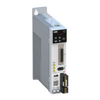
ABB E530-PT Quick Installation Manual (2 pages)
Brand:
ABB
| Category:
Servo Drives
| Size: 4 MB
Advertisement
Related Products
ABB MicroFlex e190
ABB ESP630 A3
ABB EL3060-Caldos25
ABB E2S 10
ABB E3V 20
ABB EN-R6
ABB SACE Emax E6.2-A
ABB Ekip CI
ABB Emax VF
ABB Emax2
ABB Categories
Industrial Equipment
Controller
Measuring Instruments
Battery Charger
DC Drives
More ABB Manuals
Login
Sign In
OR
Sign in with Facebook
Sign in with Google
Upload manual
Upload from disk
Upload from URL