Table of Contents
Advertisement
Quick Links
Advertisement
Table of Contents

Related Manuals for ePropulsion I-40


Summary of Contents for ePropulsion I-40
- Page 1 I-40 User Manual 2024.05 Version 1.0 Copyright © ePropulsion Technology Limited...
-
Page 3: Acknowledgement
Before use of the product, please read this user manual thoroughly to understand the correct and safe operations. By using this product, you hereby agree that you have fully read and understood all contents of this manual. ePropulsion accepts no liability for any damage or injury caused by operations that contradict this manual. - Page 4 You need to be alert, perform relevant operations reasonably, and pay attention to safety. when installing, operating, maintaining or serving ePropulsion products, there are many safety risks in the process. You need to be alert, perform relevant operations reasonably, and pay attention to safety.
-
Page 5: Product Identification
Product Identification Below picture indicates the serial numbers of the motor. Please note the position of the serial numbers and record them for access to warranty service and other after-sale services. -
Page 6: Table Of Contents
2.4 Check the packaging .................. 17 2.5 Remove the inner packaging and inspect the product ......... 18 2.6 Dispose of discarded packaging materials ..........19 3 Install the I-40 motor ..................20 3.1 Install the motor ..................20 3.1.1 Before installation ................20 3.1.2 Center the output shaft .............. - Page 7 4.1 System connection diagram ............... 27 4.1.1 System connection diagram of the single-motor ......27 4.1.2 System connection diagram of the dual-motor ......... 28 4.2 High Voltage Cables Connection ..............29 4.2.1 Making the Power Cables ..............29 4.2.2 Connecting Cables to the bus box ............ 30 4.2.2.1 Required accessories and tools ..........
- Page 8 5.5 Propulsion Page ..................50 5.5.1 Control Console ................50 5.5.2 Traction Battery ................51 5.5.3 Motor(s) ..................52 5.6 Setting ....................... 52 5.6.1 Inboard Setting ................53 5.6.2 Control console Settings ..............54 5.6.2.1 Smart throttle settings ............54 5.6.2.2 Display settings ..............
-
Page 9: Product Overview
The electric inboard motor is environmentally friendly, clean and efficient. The I-40 inboard motor is perfect for small and medium-sized recreational vessels, such as all types of yachts, leisure boats and sailboats, which range from 5 to 20m. - Page 10 Items Qty. Figure Function Hexagon Head Bolt M12x25 8pcs Lock Washer M10x2.6 4pcs Lock Washer M12x3.1 8pcs Plain Washer M10x20x2 4pcs Fasteners Motor installation Plain Washer M12x24x2.5 8pcs Hexagon Nut M10 4pcs Hexagon Head Bolt M10I-40 4pcs Heat Shrink Protect the main power cable 0.5 m Tubing after stripping it...
- Page 11 Other accessories not included in the package are also required to operate the inboard motor, such as smart throttle, smart display, battery, charger and communication cable, etc. Users can buy official accessories provided by ePropulsion from ePropulsion authorized dealers. The accessories list is shown below: Items Qty.
- Page 12 Items Qty. Figure Function Obtaining a ship's Global Positioning System (GPS) signal can provide the ship's position and speed GPS module information, helping ship managers with ship management and adjusting course plans. The 4G antenna is a kind of communication equipment. The machine realizes remote network connection through the 4G antenna to realize remote...
-
Page 13: Parts And Diagram
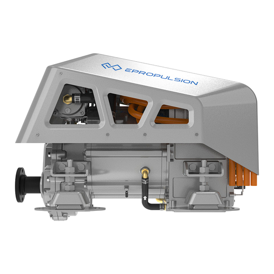
2m cable 10m Figure 1-1 1.3 Specifications Model I-40 Rated power 40kW Recommended battery ePropulsion Lithium Iron Phosphate Battery DC 96~115V (high voltage); Input voltage range DC 10.5V~16V (low voltage) Weight 93kg Dimensions (L*W*H) 673mm×453mm×476mm Cooling method Water cooling (air cooling optional) -
Page 14: Important Notes
When the high-voltage input voltage is below 96Vdc, there will be an undervoltage alarm. 1.4 Important Notes 1.4.1 Motor Selection Please follow the instructions of the boat manufacturer and ePropulsion authorised dealer in choosing a suitable inboard motor. Do not exceed the maximum power permitted, and do not overload the motor. -
Page 15: Users
1.4.3 Users 1. This product must only be operated by adults who have fully read and understood this manual. ePropulsion accepts no liability for any damage or malfunction caused by operations that contradict the content of this manual. 2. You should only use this motor system if you are also familiar with all other aspects of operating your boat. -
Page 16: Specific To This Installation
position on their wrist, ankle, or item of clothing (buoyancy aid, jacket etc). If the driver falls overboard (or accidentally leaves the helm), the lanyard will pull the kill cord off the throttle and stop the inboard. 3. Watch carefully for other vessels, swimmers and other objects in the water. Proceed with particular caution when near to harbour, shore or beach and avoid swimming areas if possible. -
Page 17: Declaration Of Conformity
Product: Electric Inboard Motor Model: I40 We Guangdong ePropulsion Technology Limited, hereby, declare that this equip ment is in compliance with the applicable Directives and European Norms, and amendments. The object of the declaration is in conformity with the following directives:... -
Page 18: Correct Disposal Of This Product
Note: This equipment has been tested and found to comply with the limits for a Class B digital device, pursuant to part 15 of the FCC Rules. These limits are designed to provide reasonable protectio n against harmful interference in a residential installation. This equipment generates, uses and c an radiate radio frequency energy and, if not installed and used in accordance with the instructio ns, may cause harmful interference to radio communications. However, there is no guarantee th at interference will not occur in a particular installation. If this equipment does cause harmful int erference to radio or television reception, which can be determined by turning the equipment off and on, the user is encouraged to try to correct the interference by one or more of the following measures: —Reorient or relocate the receiving antenna. —Increase the separation between the equipment and receiver. —Connect the equipment into an outlet on a circuit different from that to which the receiver is co nnected. —Consult the dealer or an experienced radio/TV technician for help. 1.7 Correct Disposal of this product This marking indicates that this product should not be disposed of with other household wastes throughout the EU. To prevent possible harm to the environment or human health from uncontrolled waste disposal, recycle it responsibly to promote the sustainable reuse of material resources. -
Page 19: Unpacking Steps And Notices
2 Unpacking steps and notices 2.1 Safety Notice Use appropriate safety equipment, wear gloves, protection shoes and other safety props; Ensure that all safety and measures are understood before operation; Due to the large weight of the product, ensure that at least two people operate; 2.2 Tools and equipment required for unpacking Prepare unpacking tools, such as rubber hammer, screwdriver, etc. -
Page 20: Remove The Inner Packaging And Inspect The Product
4. Take out CAN communication extension cable, CAN communication cable, main power cable, check whether the appearance is abnormal; 5. Sort out the motor, accessories, packaging and other related materials. Check the product for broken or missing parts, if there is a problem, please contact ePropulsion after-sales service for help. -
Page 21: Dispose Of Discarded Packaging Materials
2.6 Dispose of discarded packaging materials 1. Classify and recycle packaging materials, such as wood, paper, etc. 2. Follow local environmental regulations to dispose of waste materials. Make sure to read the user manual that come with the product carefully. Please follow the local material handling requirements to recycle the package, reasonable disposal, to protect the environment. -
Page 22: Install The I-40 Motor
3.1.1 Before installation 1. Check the materials: ① Motor: Check the I-40 machine structure to ensure that there is no loosening or abnormality. Arrange the main power cables, 12V power cable, and communication cable and fix them in appropriate positions for easy handling. - Page 23 In the test hoisting, the machine is stable without tilting and shaking, then formal hoisting can begin. 页 面 广东逸动科技有限公司 页 面 广东逸动科技有限公司 单位:mm Guangdong ePropulsion Technology Limited 1. Remove the cover. 2. Wrap the rope and hoist the machine 单位:mm Guangdong ePropulsion Technology Limited...
-
Page 24: Center The Output Shaft
Lifting objects hazard: pay attention to safety when hoisting equipment or objects 页 面 广东逸动科技有限公司 Guangdong ePropulsion Technology Limited 单位:mm nearby to avoid being hurt or crushed by falling objects. 88mm 100mm The cover shall be installed after the 4G antenna is installed. - Page 25 3. Move the motor so that the output shaft flange of the motor is close to the input shaft flange of the stern shaft, align the input shaft flange of the stern shaft, and compare the height difference between the output shaft and the input flange of the stern shaft. Adjust the suspension height, the ship machine shaft flange and the stern shaft input flange to adjust to the same height;...
-
Page 26: Lock The Output Shaft And Fix The Suspension
5. Flange surface fitting, flush the outlet flange with the stern shaft input flange end face, so that the positioning boss is embedded in the output shaft flange, so that the two flange faces fit, observe the size of the gap. (Note: pay attention to the mounting position of the suspension simultaneously) Positioning boss Positioning boss... - Page 27 13mm Caution: when installing, operating, maintaining or serving ePropulsion products, there are many safety risks in the process. You need to be alert, perform relevant operations 86mm 90mm reasonably, and pay attention to safety.
-
Page 28: Connect Seawater Inlet And Outlet Pipes
3.2 Connect seawater inlet and outlet pipes The machine has a water pump. According to the logo in the above figure, the water pipes with an inner diameter of 19mm are selected to be connected to the water inlet and the water outlet respectively, and the water pipes are fixed on the pagoda joint with clamps. -
Page 29: Connect The System Before Operating The Machine
4 Connect the system before operating the machine 4.1 System connection diagram 4.1.1 System connection diagram of the single-motor 43 42 1. I40电动舷外机 22. ESSA通信线1米 43. G电池充电器输出端断路器* 2. 12V电池 23. ESSA通信延长线10米 44. 电流隔离器接地线束* 3. DCDC96V-12V 24. ESSA通信终端电阻120Ω 45. 电流隔离器* 4. G电池充电器16A 25. -
Page 30: System Connection Diagram Of The Dual-Motor
4.1.2 System connection diagram of the dual-motor 43 42 1. I40电动舷外机 22. ESSA通信线1米 43. G电池充电器输出端断路器* 2. 12V电池 23. ESSA通信延长线10米 44. 电流隔离器接地线束* 3. DCDC96V-12V 24. ESSA通信终端电阻120Ω 45. 电流隔离器* 4. G电池充电器16A 25. ESSA通信终端电阻360Ω 46. G电池充电器输入端漏电保护装置* 5. G102-100电池 26. G102电池到汇流排动力线束 47. G充电器输入端熔断器与漏电 6. GPS 27. -
Page 31: High Voltage Cables Connection
"bus box to motor cable". PLEASE NOTE: Two 96V power cables are provided with the I-40. You only need to cut one of them for connection to the bus box, the other one will go directly from batteries to motor, see section 4.2.5. -
Page 32: Connecting Cables To The Bus Box
≤0.3mm 1. Fit heat shrink tubing over the joints between the terminals and the inner cables, and (separately) over the shielding layer. Leaving the joints or the shielding exposed to air may result in insulation and system failure. Please use the crimping tool corresponding to the specifications of the terminal to ensure a proper crimping process. - Page 33 (2) Connect the positive cables for Motor, Battery, Charger & DC-DC Module 1. Undo the terminal nuts, and remove the spring and flat washers 2. Install the positive cables (red sleeves) to the terminals on the lower copper bar. The battery cable goes to BAT+, the motor cable goest to MOT+, the DC-DC module goes to 96V- 2+, and the charger cable goes to CHG+ The terminal should go on first, followed by the flat washer, the spring washer and the nut.
-
Page 34: Connecting The Dc-Dc Module And 12V Battery
(5) Bus Box installation The bus box should be fitted to a flat surface, as far from sources of moisture and heat as is reasonably practical. Depending on the mounting surface, M6 screws or bolts can be used to fix it in place. M6 locking torque is 8N.m. IMPORTANT. -
Page 35: Installation Steps
4.2.3.2 Installation Steps Step 1: Connecting the Bus Bar with the DC-DC Module See 4.2.2 if not already done. Figure 4.7 Step 2: Connecting the DC-DC Module Communication Cable Use the 3-way T connector included in the DC-DC package to connect the DC-DC communication cable to the inboard motor's communication cable. -
Page 36: Connecting The G102-100 Battery Bank
4.2.4.1 Required Accessories and Tools ① G102-100 battery bank (at least 4 G102 batteries are needed, connected in parallel, to operate I-40 motor) ② Bus box part completed in step 4.2.2 Ensure that the main switch is turned off before connecting the batteries. -
Page 37: Connecting The Inboard Motor's Main Power And 12 Volt Cables
4.2.5 Connecting the inboard motor's Main Power and 12 volt Cables 4.2.5.1 Required Accessories and Tools ① Inboard motor ② Bus box and 96V Motor power cable connected in 4.2.2 ③ 2nd 96V Motor power cable not cut or connected to bus box ④... - Page 38 Step 2: Connecting the 2nd High Voltage Power Cable The 2nd 96V power cable (supplied with I-40) does not need to be cut, nor routed via the bus box. It's connected directly to the battery and the second motor plug, following same steps as above.
-
Page 39: Connection Of Communication Devices (Helm, Throttle Etc)
① GPS module ×1 ② Smart throttle ×1 ③ Smart display 5'' ×1 ④ G102-100 battery ×4 (4 is the minimum for single I-40 inboard installations. More may be needed depending on range requirements.) ⑤ CAN Communication 1m Extension Cable ×4 ⑥... -
Page 40: Smart Throttle Connection
Smart display Smart throttle eSSA Communication 3-way T-connector eSSA Communication Cable 1m eSSA Communication 5-way T-connector eSSA Communication Terminators Figure 4.16 4.3.2.2 Smart throttle connection Each smart throttle has a BUS port and DUAL port at the bottom. when being used Connect to system as a dual throttle Figure 4.17... -
Page 41: Grounding
18mm All operations must be done without power. Do not connect or disconnect the cables while there is power. 116mm 120mm 4.4 Grounding In order to ensure safety and stability of system operation, the I series inboard motor (with a 5m grounding line), DCDC module, G102-100 battery, and 12V battery (purchased by the user) must be grounded during system installation. -
Page 42: External 4G & Gps Antenna (If Required)
4.5 External 4G & GPS Antenna (if required) The X-series inboard motor has integrated 4G and GPS modules under the top cover. Avoid covering this area if possible. If the installation does affect signal strength, external 4G and/or GPS modules can be used (not supplied, available as accessories). 4.5.1 Installation of the 4G Antenna Step 1: Undo the four screws in the top cover and remove. -
Page 43: Installation Of The External Gps Module
Step 4: Fix the 4G antenna on the boat (outdoors). There are two fixing options, as shown in the following images. Antenn Antenn Steel expansion bolt M8*50 (4PCS User provided) Clip Non-concrete wall Lead out Lead out ∅ ∅ Holding rod low loss low loss Diameter... - Page 44 • 3M Adhesive Attachment Attach the double-sided adhesive pad to the back of the GPS module as shown below. Make sure the chosen location is clean and dry, then stick the module in place. The bond will take a few hours to acquire full strength. Fixed adhesive sticker External GPS module Figure 4.20 GPS external module adhesive pad fixing...
-
Page 45: Communication Terminator Connection
4.6 Communication Terminator Connection Communication terminators are needed to ensure stable communication within the system. Different combinations are required, depending on how many motors are in the system and whether an external GPS module is connected, as shown in the table below. The resistance value of the terminator is marked on the tail. -
Page 46: Operation
5 Operation 5.1 Smart Throttle Button Functions (single & double throttles) Single-throttle operation Button Function Press and hold down this button for 1 second to power the system on or off. Power Switch console (when two throttles are fitted): When the system is turned on, press the Power button twice on the inactive console to activate it. - Page 47 Dual-throttle operation Button Function Press and hold down this button for 1 second to power the system on or off. Power Switch console: When the system is turned on, press the Power button twice on the inactive console to activate it. Direction holding function or anchor mode: Press twice to enter Hold Hold mode, and when in Hold mode press once to exit.This...
-
Page 48: Starting The System
Kill Switch Notes Kill Switch can be placed on either end of the Smart Throttle, depending which way throttle is facing. Motor will not work without kill switch in place. Kill switch should be removed when motor is turned off. In an emergency, motor can be stopped by pulling kill switch off throttle. -
Page 49: System Problem Feedback Method After Startup
5.2.2 System problem feedback method after startup If the smart throttle chirps after the system is started and the display displays an error message, refer to Troubleshooting (section 5.11) to solve the problem. 5.3 Perform initial configuration Step 1: Read the system devices After all accessories are assembled, power on, turn on the smart throttle, and the Smart display will automatically read the Serial Numbers (SN) of the devices in the system. - Page 50 1. Configuration display When there are two consoles, the display will display two consoles. By default, the console where the current display is located is Console A. 2. Configure smart throttle When it is a single-throttle, manually click any button of the throttle to match successfully. When it is a dual-throttle, click any button of the left and right throttles respectively to match successfully.
-
Page 51: Home Page
5.4 Home Page Function Description Setting page Click to go to the setting page. Home page Click to go to the home page. Propulsion page Click to go to the propulsion page. Warning When the system fails, it will prompt a fault icon. System status READY indicates that the system is ready to start. -
Page 52: Propulsion Page
5.5 Propulsion Page The propulsion system page is accessed by clicking the boat icon, just to the right of top centre on the screen. 5.5.1 Control Console Click on the console icon to view the accessories for each console. -
Page 53: Traction Battery
If an accessory fails, its icon will turn orange or red. Click the fault icon to view the problem in more detail. 5.5.2 Traction Battery Click on the Traction Battery icon to view the remaining power, voltage, and current. -
Page 54: Motor(S)
5.5.3 Motor(s) Click on the Motor icon(s) to view current power, rotational speed and cumulative run time. 5.6 Setting The Settings page is accessed by clicking the gear icon, just to the left of top centre on the screen. This covers three groups of settings: Inboard, Control and General. -
Page 55: Inboard Setting
Button Function Click to enter the propulsion setting page, where you can access the Inboard propulsion, steering and DC-DC output settings Click to enter the console setting page, you can set single-throttle CONTROL assembly, dual-throttle FN function, Smart display, etc. Click to enter the general setting page to set firmware update, GENERAL maintenance, connectivity and more. -
Page 56: Control Console Settings
5.6.2 Control console Settings 5.6.2.1 Smart throttle settings 1. Single-throttle Settings Function Description Click and set the smart throttle installation mode to starboard Starboard installation. If it springs back, the setting fails. Click and set the smart throttle installation mode to port installation. Port If it springs back, the setting fails. - Page 57 2. Set dual-throttle Function Description None Set the FN function of smart throttle as invalid after clicking. Set the FN function to synchronise left and right hand throttles when clicked. Sync With Sync on, if the left and right throttle power settings are similar, the system will make them the same.
-
Page 58: Display Settings
This will change the display on the home page. Switch speed and distance units between knots (nautical miles per Units hour), km/h (kilometres per hour) and mph (miles per hour). This will change the display on the home page and ePropulsion setting page. -
Page 59: General Settings
5.6.3 General settings 5.6.3.1 System firmware information Function Description System version Display the system/software version. Serial Click Device List to go to the device serial number list page. You can number view all device SN and software and hardware version. When there is a new version available, you will be prompted with the content of the new version and the estimated time to update.. -
Page 60: Maintenance - All Maintenance Timing Tips
Device list page 1. Click Reset to reset the device original factory settings. 2. Device List displays the SN and software and hardware versions of all components of the propulsion. 5.6.3.2 Maintenance - All maintenance timing tips The system automatically calculates the maintenance time based on various maintenance items. -
Page 61: Connectivity
I-40 offers connectivity capabilities by communicating with the ePropulsion cloud through its 4G antenna. You can link your product to the ePropulsion Link, a user-friendly software designed for personal boat owners, enabling them to monitor their boat's status remotely on their mobile devices. - Page 62 To check if a new software version is available, access the boat display through the following path: Settings > General > System Info. If your ePropulsion system is connected to the ePropulsion Link, you will also receive notifications about new software versions within the ePropulsion Link. OTA access can be found on the propulsion system page.
-
Page 63: Motor Operation
30 minutes. After a successful installation, you will see that your system is running the latest version on the boat display, and you will receive a notification of the successful update within the ePropulsion Link. 5.7 Motor operation 5.7.1 Start... -
Page 64: Troubleshooting
5. The battery is empty. 6. The inboard motor malfunctions (e.g.the motor is blocked or the battery voltage drops below 33V). 2. Rotating parts can cause severe injury or death. Never wear jewelry, unbuttoned cuffs, ties or loose-fitting clothing and always tie long hair back when working near moving/ rotating parts such as the flywheel or PTO shaft. -
Page 65: System Faults
5.8.2 System faults Module Fault Solution 1. Check the external wiring. Encoder fault P101003 2. Replace the rotary encoder. 3. Replace the motor controller. 1. Check the external wiring. Power tube pass- P100F03 2. Check the insulation of the motor. through failure 3. - Page 66 Module Fault Solution The generator is generally P100912 Check the battery SOC undervoltage 1. Check the operating condition. The MOS 2. Check whether the heat dissipation is severely P100003 channel is blocked. overtemperature 3. Check the coolant level 1. Overhaul the motor or transmission The motor system.
- Page 67 Module Fault Solution 1. Do not need to be processed if it is recoverable CAN_B BUSOFF P130941 2. Check whether the cable is in poor contact 1. Do not need to be processed if it is recoverable CAN_C BUSOFF P130A43 2.
- Page 68 Module Fault Solution 1. Recalibrate away from strong Abnormal throttle magnetic fields H120203 calibration data 2. If it occurs repeatedly, contact after- sales treatment Abnormal throttle Smart throttle H120003 Stay away from strong magnetic fields Angle Abnormal safety Check that the safety switch is properly H120403 switch sucked into the slot...
-
Page 69: Maintenance
6 Maintenance 6.1 Repair and maintenance: Maintenance cycle Every interval First maintenance thereafter Components Items Work 50 hours 100 hours 250 hours 1000 hours (or 3 (or 6 (or 1 year) (or 4 years) months) months) Suspension Foot pads of repair and Check/Replace ●... -
Page 70: Part Of The Repair And Maintenance Guide
页 面 加工余量 广东逸动科技有限公 0.05 0.002 N10074 机型 0.02 0.276in 0.001 N10024 完成日期 2023/4/15 页 面 单位:mm Guangdong ePropulsion Technology Lim 广东逸动科技有限公司 + 0.10 + 0.004 N10024 完成日期 2023/4/15 单位:mm Guangdong ePropulsion Technology Limited 22.00mm 0.866in 23mm0.906in 0.05 0.002 0.02 0.315in 0.001... -
Page 71: Regular Cleaning Of Heat Exchanger
Please pay attention to the placement of the container to prevent the coolant from leaking and polluting the environment. 3. Use the movable wrench to remove the I-40 vent pipe on the gearbox (be careful not to scratch the sealing ring of the I-40 vent pipe);... -
Page 72: Replace Glycol
8. Install the external circulation water pipe to the pagoda head of the heat exchanger, and lock the adjustable clamp; 9. Tighten the I-40 vent pipe with a movable wrench, and pay attention not to press the sealing ring of the I-40 vent pipe during installation;... - Page 73 2. Unscrew the heat exchanger vent; 3. Unscrew the bottom sealing plug and drain the ethylene glycol inside the machine; 4. Twist the sealing plug and tighten the torque by 12Nm; 5. Inject about 1550ml of ethylene glycol from the top of the heat exchanger until the liquid level reaches the position shown in the figure.
-
Page 74: List Of Fasteners
6.3 List of fasteners Assembly to be Locking reference Items Specifications fastened moment (Nm) Hex socket flat head Cover M5x12 1.5~2.0 screw Hex socket round head Deflector series M5x10 1.5~2.0 screw Hex socket round head Fan fasteners M5x10 1.5~2.0 screw Suspension foot Hexagon bolt M10×18... -
Page 75: Warranty
(the “ePropulsion Service Partners”) with minimum maintenance charge per occurrence. In all warranty cases, ePropulsion will only bear the repair cost and other costs (such as those related to product installation, disassemble, transportation, financing, rental, etc.) as a direct result forof issues covered by the Limited Warranty only. -
Page 76: Out Of Warranty
The average temperature is calculated using the Arrhenius equation; this means that higher temperatures are given a greater weighting. 7.1 Out of Warranty ePropulsion may refuse a warranty claim if: • Any improper operation contradicts what is written in the user manual; • Accident, misuse, dropping, improper care or storage, willful abuse, physical damage, overcharging, over discharging, or unauthorized repair;... -
Page 77: Limited Warranty Claim Procedures
6. In case your warranty claim be rejected, a repair/replace cost and fee with round trip delivery cost will be estimated and sent to you for confirmation. ePropulsion Service Partners will only begin the work after your written confirmation. - Page 79 WARRANTY CARD ePropulsion Control System (*In order to validate warranty, please fill in this form first and read the Warranty Policies.) OWNER INFO. Owner Name Address Phone Email DEALER INFO. Store Name Address Phone Email PRODUCT INFO. Date of Purchase (mm/dd/yyyy)
- Page 81 Thanks for reading this user manual. If you have any concerns or find any problems while reading, please don't hesitate to contact us. We are delighted to offer service for you. Guangdong ePropulsion Technology Limited Webseite: www.epropulsion.com E-Mail: service@epropulsion.com...
Need help?
Do you have a question about the I-40 and is the answer not in the manual?
Questions and answers