Table of Contents
Advertisement
Quick Links
OPERATORS' MANUAL
MIG 280/4
Part No. 8002
Version 1.1 – Last updated 01.01.2021
IMPORTANT
Please read these instructions carefully before attempting to use this equipment.
Retain this manual and keep it to hand for quick reference. Pay particular attention to the safety instructions.
Contact your distributor if you do not fully understand this manual.
Advertisement
Table of Contents

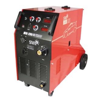
Summary of Contents for SWP REDLINE MIG 280/4 TURBO
- Page 1 OPERATORS’ MANUAL MIG 280/4 Part No. 8002 Version 1.1 – Last updated 01.01.2021 IMPORTANT Please read these instructions carefully before attempting to use this equipment. Retain this manual and keep it to hand for quick reference. Pay particular attention to the safety instructions. Contact your distributor if you do not fully understand this manual.
- Page 2 RESPONSIBILITY The user shall inspect the machine. If the machine is faulty, immediately shut down. Any faulty parts shall be changed promptly. When repair or change, the manufacturer advised the user to change the part forward the require in written or calling form to the licensed distributors.
-
Page 3: Table Of Contents
CONTENTS General Safety MAIN CHARACTERISTIC AND SUITABLE RANGE MAIN TECHNICAL DATA FUNCTION 7 INDICATING AND WARNING ON THE MIG-280/4 CONTROL PANEL SAFE AND INSTALLATION CAUTION EXPLANATION OF INSTALLATION OPERATIONS SUGGESTED WELDING CRITERION WORKING ELEMENTS 10 MAINTENANCE 11 TROUBLES AND REMEDY 12 ENLARGE THE LENGTH OF THE WELDING CABLE 13 TRANSPORTATION, STORAGE AND ENVIRONMENT CONDITIONS 14 QUALITY GUARANTEED... -
Page 4: Safety Precautions
SAFETY PRECAUTIONS Follow these precautions carefully. Improper use of any welder can result in injury or death. ONLY CONNECT WELDER TO A POWER SOURCE FOR WHICH IT WAS DESIGNED. The specification plate on the welder lists this information. When welding outdoors only use an extension cord intended for such use. - Page 5 INTRODUCTION We do very appreciated for your selecting our products. It can be composed the MIG-280/4 CO ARC Welding system equipped with wire feeder and welding gun. It has many characteristic such as easy Arc starting, good Arc springiness, adjustable arc thrusting, low splash, good welding form, easy welding operation.
-
Page 6: Main Characteristic And Suitable Range
1. MAIN CHARACTERISTIC AND SUITABLE RANGE This kind of welding power Model MlG-280/4 is taken foreign advanced technology to develop and manufacture. It has the perfect performance of high quality, good reliability, quick speed of welding current, steady welding process, low splash and good welding form. Anyway, it becomes the welding very easy. -
Page 7: Function
FUNCTION 3.1 Adjusting function for the welding voltage and welding current MIG-280/4 supply the adjusting range as follows: Welding voltage: 16V ± 3V-40V ± 3V use Voltage rough control switch and Voltage fine control switch Welding current: 40A~200A use the current adjusting knob 3.2 36Vac-3A/l 10W power function When you use the CO welding machine, you may generally equip with gas heating source. -
Page 8: Indicating And Warning On The Mig-280/4 Control Panel
INDICATING AND WARNING ON THE MIG-280/4 CONTROL PANEL (FRONT) 4.1 Indicating and adjusting WARNING LIGHT SPOT TIME PULSE TIME CURRENT DIAGRAM 1... - Page 9 PANEL (REAR) HEATING PLUG CONNECT CO METER DIAGRAM 2 Open the right side panel door to view wire feeder and weld wire bracket (below) CRATER TIME WELD WIRE BRACKET DIAGRAM 3 WIRE FEEDER...
-
Page 10: Safe And Installation Caution
4.1.1 Power indicating If the indicating light is on the control circuit connects the power already. Warning In order to remind the operator, we design the warnings as following: • excess temp ln the condition of more than 40ºC temperature, large current is used continuously (12>200A), efficiency radiator temperature is more than 80 ±... - Page 11 DIAGRAM 4 DIAGRAM 5 The power source is 220Vac/(50~60Hz). The yellow/green double cable is grounding cable. Be sure to connect the yellow/green double cable into the grounding connection in the welding locale. Another way is selecting the M8 bolt on the back on the machine and connect the grounding as diagram 5. •...
-
Page 12: Operations
7. OPERATIONS • ON/OFF indicating switch on the FRONT panel. • Confirm the specification of the wire feed hose. • Confirm the specification of nib base. It affects the extended length of the wire. • Confirm the specification of nib. It affects the electric resistance. •... -
Page 13: Working Elements
WORKING ELEMENTS Diagram for the MIG-280/4 working elements. Diagram 9. 10. MAINTENANCE Check the safety measure be efficiency. Get rid of the dust for the power source (For example, dry compressed air). Before operating check the +/– connectors of the power panel if they are relaxed. Check the connection between the grounding cable and plug if they are relaxed (If relaxed, the serious heating will damage the quick connectors). -
Page 14: Enlarge The Length Of The Welding Cable
12. ENLARGE THE LENGTH OF THE WELDING CABLE The length of the welding cable includes the total length of the welding circuit including the cables between the positive (+) of the power source. The cables longer, the section area thinner, it caused large voltage reducing and large voltage loss. -
Page 16: Packing List
15. PACKING LIST MIG-280/4 Welding machine Adapter connector + 20mm cable Welding torch Flow meter Operation instructions Certificate of quality CERTIFICATE OF QUALITY Name of product: CO Semi-auto ARC Welding Machine Packing No: Test results of this welder fulfils technical requirements and its release from the works is granted Inspector Date National Distribution Centre...


Need help?
Do you have a question about the REDLINE MIG 280/4 TURBO and is the answer not in the manual?
Questions and answers