
Related Manuals for Nord Drivesystems SK PAR-3H


Summary of Contents for Nord Drivesystems SK PAR-3H
- Page 1 BU 0040 – en Parameterisation units for drive electronics Manual with installation instructions...
-
Page 2: Version List
BU 0040 Order no.: 6070402 Device types SK TU5-CTR, SK TU5-PAR, SK TU3-PAR, SK TU3-CTR, SK PAR-5H/A, SK PAR-3H/E, SK CSX-3H/E For series: NORDAC START, NORDAC BASE NORDAC FLEX, NORDAC LINK, NORDAC PRO, NORDAC ON Version list Title, Order number... -
Page 3: Other Applicable Documents
Any editing or amendment or other utilisation of the document is prohibited. Publisher Getriebebau NORD GmbH & Co. KG Getriebebau-Nord-Straße 1 • 22941 Bargteheide, Germany • http://www.nord.com Fon +49 (0) 45 32 / 289-0 • Fax +49 (0) 45 32 / 289-2253 Member of the NORD DRIVESYSTEMS Group BU 0040 en-4923... - Page 4 Parameterisation units for drive electronics – Manual with installation instructions BU 0040 en-4923...
-
Page 5: Table Of Contents
Table of Contents Table of Contents General ................................. 8 Device characteristics ........................8 Delivery ............................11 Scope of delivery..........................12 Accessories ............................13 Intended use ............................ 13 Selection and qualification of personnel ................... 14 1.6.1 Qualified personnel ......................14 1.6.2 Qualified electrician ...................... - Page 6 Parameterisation units for drive electronics – Manual with installation instructions 5.1.2 Parameterisation ........................ 62 5.1.3 Param. management ......................63 5.1.4 Options ..........................65 Error an warning messages ........................67 Error messages (ControlBox (SK TU5-CTR)) .................. 67 Error messages (ParameterBox)...................... 67 Warnings (ParameterBox) ........................
-
Page 7: List Of Illustrations
List of illustrations List of illustrations Figure 1: SK PAR-5H assembly diagram ......................22 Figure 2: Exploded-view diagram SK PAR-5H assembly ..................22 Figure 3: SK PAR-5A installation dimensions ......................27 Figure 4: Installation options for the SK PAR-5A on a NORDAC FLEX ..............27 Figure 5: Electrical connection of the SK PAR-5A to the terminal strip .............. -
Page 8: General
Parameterisation units for drive electronics – Manual with installation instructions 1 General The NORD parametrisation units enable parameterisation, control and display of the operating parameters of the frequency inverters and motor starters from Getriebebau NORD GmbH & Co. KG. They are available in different versions. Further information on the respective properties of the individual units can be found in Chapter 1.1 "Device characteristics". - Page 9 5 V DC or 24 V DC power supply can be used by the device Restriction: display only for one selectable operating parameter For SK PAR-3H / -3E, only 3 parameter sets can be stored. Only SK PAR-5A BU 0040 en-4923...
- Page 10 Parameterisation units for drive electronics – Manual with installation instructions Product type SK TU3-PAR SK TU5-PAR SK TU3-CTR SK TU5-CTR Variant Plug-on Plug-on Plug-on Plug-on Category ParameterBox ParameterBox ControlBox ControlBox Legend Function / feature = Present = Not present Operation ...
-
Page 11: Delivery
1 General 1.2 Delivery Examine the device for transport damage or loose components immediately on delivery / unpacking. In case of damage, contact the carrier immediately and arrange for a careful survey. Important! This also applies if the packaging is undamaged. NOTICE Defect in the device If the device is connected to the incorrect frequency inverter or operated with the incorrect accessories,... -
Page 12: Scope Of Delivery
– RJ12, length approx. 1.5 m SK PAR-5A 275281714 SK PAR-3E 275281414 • Including connection cable: – RJ12-RJ12, length approx. 2 m SK PAR-3H 275281014 • Including connection cable: – RJ12-RJ12, length approx. 2 m – USB, length approx. 1 m SK CSX-3E 275281413 •... -
Page 13: Accessories
They have been developed and configured for use with the following frequency inverters from Getriebebau NORD GmbH & Co. KG. Parameterisation unit Frequency inverters Assembly type SK PAR-3H NORDAC FLEX, NORDAC PRO, NORDAC LINK, SK CSX-3H Handheld NORDAC ON, NORDAC BASE,... -
Page 14: Selection And Qualification Of Personnel
Parameterisation units for drive electronics – Manual with installation instructions 1.6 Selection and qualification of personnel The parameterisation units may only be installed and commissioned by qualified electricians. 1.6.1 Qualified personnel Qualified personnel includes persons who due to their specialist training and experience have sufficient knowledge in a specialised area and are familiar with the relevant occupational safety and accident prevention regulations as well as the generally recognised technical rules. -
Page 15: Safety And Warning Information
1 General 1.7 Safety and warning information Use the parameterisation units and frequency inverters from the NORD DRIVESYSTEMS Group only for their intended purpose (see chapter 1.5 "Intended use" on page 13). To ensure safe operation of the parameterisation units, observe all of the instructions in this manual, and in particular the warning information in the other applicable documents (see chapter 8.2 "Further... -
Page 16: Explanation Of Markings
Parameterisation units for drive electronics – Manual with installation instructions 1.8 Explanation of markings DANGER Indicates an immediate danger, which may result in death or very serious injury if it is not avoided. WARNING Indicates a dangerous situation, which may result in death or serious injury if it is not avoided. CAUTION Indicates a dangerous situation, which may result in minor injuries if it is not avoided. -
Page 17: Type Code / Nomenclature
1 General 1.10 Type code / nomenclature Unique type codes have been defined for the individual parameterisation units, giving details of the device type, its electrical data, protection class and mounting variant A distinction is made between the following groups: ParameterBox (handheld) ControlBox (plug-on variant) 1.10.1 Name plate... -
Page 18: Type Code Parameterisation Units
Parameterisation units for drive electronics – Manual with installation instructions 1.10.2 Type code parameterisation units SK TU5-PAR Option type: PAR = ParameterBox (removable control unit) CTR = ControlBox (removable control unit) Group: TU5 = Technology unit (SK 5xxP) TU3 = Technology unit (SK 5xxE) SK PAR-5H 5H =... -
Page 19: Connection And Assembly
NOTICE Damage to the PC The SK PAR-3H/-5H/-5A and SK TU5-PAR ParameterBox must never be connected to a device and to the PC at the same time, as this may result in damage, in particular to the PC. BU 0040 en-4923... -
Page 20: Electrical Connection
Therefore, the parameterisation unit should only be RJ12 (RS485) integrated as the first or last participant. The SK PAR-3H parameterisation unit is connected to a PC via the unit’s integrated USB interface. This connection is also used for the unit’s power supply. -
Page 21: Par-5H
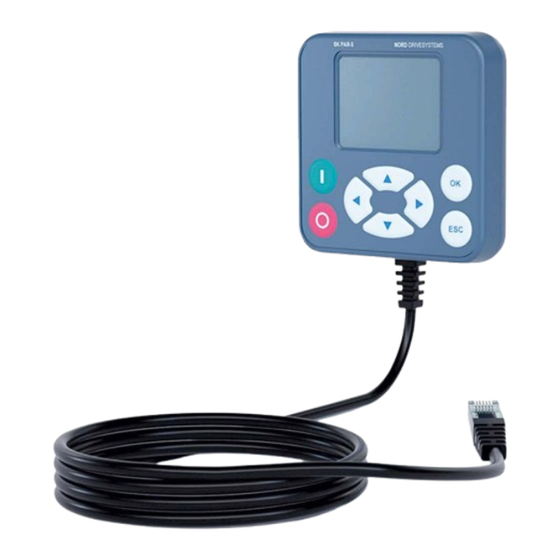
2 Connection and assembly 2.2 SK PAR-5H SK PAR-5H ParameterBox compact parameterisation unit for direct connection to the frequency inverter or installation in a control cabinet or a control panel. The connection cable is permanently installed on one side of the parameterisation unit and equipped with a RJ12 plug on the other side. -
Page 22: Figure 1: Sk Par-5H Assembly Diagram
Parameterisation units for drive electronics – Manual with installation instructions Figure 1: SK PAR-5H assembly diagram Front view Back view Figure 2: Exploded-view diagram SK PAR-5H assembly BU 0040 en-4923... -
Page 23: Electrical Connection
2 Connection and assembly 2.2.2 Electrical connection NOTICE Possible malfunction and damage to the ParameterBox in case of incorrect connection To avoid damage to the ParameterBox, do not connect the ParameterBox to a PC and a frequency inverter in parallel. Connection to a PC The ParameterBox (communication and power supply) is connected by means of a standard USB/USB-C... -
Page 24: Csx/Par-3E
Parameterisation units for drive electronics – Manual with installation instructions 2.3 SK CSX/PAR-3E SK CSX-3E The SK CSX-3E SimpleControlBox is a compact control device for installation in a control panel and direct connection to the frequency inverter with RJ12 diagnostics socket. A standard RJ12 patch cable (modular cable RJ12 (6/6) - RJ12 (6/6), 1:1 assigned) with a length of up to 3 m can be used as the connection cable. -
Page 25: Electrical Connection
Therefore, the ParameterBox should only be integrated as the first or last participant. RJ12 (RS485) In contrast to the SK PAR-3H handheld variant, the connection of the SK PAR-3E ParameterBox to a PC is Parameterisation unit back side not possible. -
Page 26: Par-5A
Parameterisation units for drive electronics – Manual with installation instructions 2.4 SK PAR-5A The SK PAR-5A ParameterBox is a compact parameterisation unit for attachment to the NORDAC FLEX on an M25 cable gland. The assembly and electrical connection are carried out directly at the frequency inverter. -
Page 27: Figure 3: Sk Par-5A Installation Dimensions
2 Connection and assembly Figure 3: SK PAR-5A installation dimensions Figure 4: Installation options for the SK PAR-5A on a NORDAC FLEX BU 0040 en-4923... -
Page 28: Electrical Connection
Parameterisation units for drive electronics – Manual with installation instructions 2.4.2 Electrical connection NOTICE Possible malfunction and damage to the ParameterBox in case of incorrect connection To avoid damage to the ParameterBox, do not connect the ParameterBox to a PC and a frequency inverter in parallel. -
Page 29: Figure 5: Electrical Connection Of The Sk Par-5A To The Terminal Strip
2 Connection and assembly Figure 5: Electrical connection of the SK PAR-5A to the terminal strip Terminal Designation Colour Blue 24 V output Brown SYS H Black SYS L Grey RS485+ Green RS485- Table 2: Connection terminal details BU 0040 en-4923... -
Page 30: Csx-3E
Parameterisation units for drive electronics – Manual with installation instructions 2.5 SK CSX-3E These technology units are only suitable for use with the NORDAC PRO (SK 5xxE). 2.5.1 SK TU3-CTR SK TU3-CTR ControlBox used commissioning, configuring and controlling the NORDAC PRO (SK 5xxE). It is mounted directly slot technology units. -
Page 31: Mechanical Installation On A Nordac Pro (Sk 5Xxe)
2 Connection and assembly 2.5.3 Mechanical installation on a NORDAC PRO (SK 5xxE) Information Das Einsetzen oder Entfernen der Module sollte nur im spannungsfreien Zustand erfolgen. Die Steckplätze sind nur für die dafür vorgesehenen Module nutzbar. Eine vom Frequenzumrichter entfernte Montage der Technologiebox ist nicht möglich, sie muss unmittelbar am Frequenzumrichter aufgesteckt werden. -
Page 32: Tu5-Xxx
Parameterisation units for drive electronics – Manual with installation instructions 2.6 SK TU5-xxx These technology units are only suitable for use with the NORDAC PRO (SK 5xxP). 2.6.1 SK TU5-CTR SK TU5-CTR ControlBox used commissioning, configuring and controlling the NORDAC PRO (SK 5xxP). It is mounted directly on or on the the slot for technology units SK CU5... -
Page 33: Mechanical Installation On A Nordac Pro (Sk 5Xxp)
2 Connection and assembly NOTICE Possible malfunction and damage to the ParameterBox in case of incorrect connection To avoid damage to the ParameterBox, do not connect the ParameterBox to a PC while it is connected to a frequency inverter. 2.6.3 Mechanical installation on a NORDAC PRO (SK 5xxP) Information Das Einsetzen oder Entfernen der Module sollte nur im spannungsfreien Zustand erfolgen. -
Page 34: Display And Operation
Parameterisation units for drive electronics – Manual with installation instructions 3 Display and operation 3.1 ParameterBox 3.1.1 Display After the ParameterBox has been commissioned for the first time, there will be a request for the menu language, German or English. An automatic “Bus scan”... - Page 35 3 Display and operation Status window In the status window of menu level 1, an interface status of all frequency inverters connected to the BUS is displayed. The USS address, the interface status and the current setpoint of each object are displayed in percent. Frequency inverter with USS address used...
-
Page 36: Operation
Parameterisation units for drive electronics – Manual with installation instructions 3.1.2 Operation Keys Explanation Arrow Use the arrow keys (left/right) to go through the menu levels and the individual menu keys items. (left/right) Simultaneously press the ◄ and ► keys to go one level back. Arrow The content of individual parameters can be changed with the arrow keys (up/down). -
Page 37: Controlling The Frequency Inverter
3 Display and operation 3.1.3 Controlling the frequency inverter The frequency inverter’s speed and direction of rotation can be fully controlled via the ParameterBox. Depending on the frequency inverter series, different settings are required for this. Series Setting P509 Comment NORDAC Control via the ParameterBox is only possible if there is no enable via {0} “Contr.term. - Page 38 Parameterisation units for drive electronics – Manual with installation instructions SK PAR-5H SK TU5-PAR STOP Keyboard functions Reverse the (No enable) identical with SK PAR-5H direction of rotation START Save the current (Enable) frequency ▲ = Increase frequency, ▼ = Reduce frequency If the frequency inverter is enabled in this mode, the parameter set selected for this frequency inverter in Menu >Parameterization<...
-
Page 39: Simple)Controlbox
3 Display and operation Menu structure of the ParameterBox The menu structure consists of various levels that are each arranged in a ring structure. Pressing the ENTER key takes you to the next level. To return, press the ◄ and ► arrow keys simultaneously. 53xP 2.2kW/230V/1 BSC Fi/Hz 45.0... -
Page 40: Csx-3X And Sk Tu3-Ctr Display
Parameterisation units for drive electronics – Manual with installation instructions 3.2.1 SK CSX-3x and SK TU3-CTR display After connecting/assembling the box and switching on the frequency inverter’s mains voltage (or the control voltage), communication between the frequency inverter and box is automatically established. - Page 41 3 Display and operation 7-segment LED display (4-digit) Operating mode Comment Ready for Display of 3 static underscores operation When underscores are flashing slowly: • Without • Frequency inverter is not ready for present operation (e.g.:) setpoint – Switch-on inhibit: Function “Safe pulse block”...
-
Page 42: Tu5-Ctr Display
Parameterisation units for drive electronics – Manual with installation instructions 3.2.2 SK TU5-CTR display Load display of the FI (with 100% value) Parameter set display 5-Digit 7-segment display with prefix and 4 x point 3-digit 14-segment display for units Enable right and enable left 4 status display for the frequency inverter Status displays Fault present... - Page 43 3 Display and operation 7-segment LED display (5-digit) Operating mode Comment Ready for Display of 3 static underscores operation When underscores are flashing slowly: • Without • Frequency inverter is not ready for operation present (e.g.:) setpoint – Switch-on inhibit: Function “Safe pulse block”...
-
Page 44: Operation
Parameterisation units for drive electronics – Manual with installation instructions 3.2.3 Operation Keys Explanation START To switch on the frequency inverter. The frequency inverter is now enabled with the set jog frequency (P113). A possibly preset minimum frequency (P104) is supplied as a minimum. -
Page 45: Control With The (Simple)Controlbox Sk Csx-3X And Sk Tu3-Ctr
3 Display and operation 3.2.4 Control with the (Simple)ControlBox SK CSX-3x and SK TU3-CTR The frequency inverter can only be controlled via the (Simple)ControlBox, if it has not been previously enabled via the control terminals or via a serial interface (P509 = 0 and P510 = 0). If the START key is pressed, the frequency inverter changes to the operating display (selection P001). -
Page 46: Controlling With The Controlbox Sk Tu5-Ctr
Parameterisation units for drive electronics – Manual with installation instructions Information Notes on the SimpleControlBox (SK CSX-3x) When used on frequency inverters of the SK 500E series, no technology unit (SK TU3-PAR) must be plugged in. Otherwise, communication errors are to be expected. 3.2.5 Controlling with the ControlBox SK TU5-CTR The frequency inverter can only be controlled via the ControlBox, if it has not been previously enabled via the control terminals or via a serial interface (P509 = 0 and P510 = 0). - Page 47 3 Display and operation Further functions can be accessed via combinations of two or more keys: If the inverter is switched on: switchover to the parameter level Trigger quick stop by enabling with the keyboard Reset the value to the default setting Flashing: Only the last 5 bars flash: Warning, inverter overloaded.
-
Page 48: Parameterisation
Parameterisation units for drive electronics – Manual with installation instructions 4 Parameterisation 4.1 Parameterisation with the ParameterBox The parameterisation mode can be accessed by selecting the menu item >Parameterization< in level 1 of the ParameterBox. Pressing the ENTER key accesses the parameter level of the connected frequency inverter. -
Page 49: Acceleration Time
4 Parameterisation Screen layout during paramterisation If the setting of the parameter is changed, the value flashes until it is confirmed with the ENTER key. To retain the factory settings for the parameter to be edited, the ▲ and ▼ arrow keys must be pressed simultaneously. -
Page 50: Data Transfer With Nordcon
In this mode, communication of the ParameterBox with the PLC (SPS) of a suitably equipped frequency inverter from NORD DRIVESYSTEMS (e.g. SK 540E / SK 545E) is possible so that the PLC can use the entire display as a display interface. - Page 51 NOTICE Damage to the PC The SK PAR-3H/-5H/-5A and SK TU5-PAR ParameterBox must never be connected to a device and to the PC at the same time, as this may result in damage, in particular to the PC. The following components are necessary for the connection ParameterBox PC / laptop: USB 2.0 connection cable...
-
Page 52: Figure 6: Nordcon Display: Bus Scan
Parameterisation units for drive electronics – Manual with installation instructions Figure 6: NORDCON display: Bus scan All NORDCON parameterisation functions are now available. Information Pre-assembly of a frequency inverter data set Only storage objects saved in the frequency inverter (data sets) can be detected and processed by the NORDCON parameterisation software. -
Page 53: Parameterisation With The (Simple)Controlbox
4 Parameterisation 4.2 Parameterisation with the (Simple)ControlBox 4.2.1 Parameterisation with the SK TU3-CTR, SK CSX-3H/E The parameterisation of the frequency inverter can be carried out in the various operating statuses. All parameters can always be changed online. The switchover to parameter mode is performed in different ways depending upon the operating status and the enabling source. - Page 54 Parameterisation units for drive electronics – Manual with installation instructions Changing parameter values To access the parameter range, press one of the ▼ or ▲ arrow keys. The display changes to the menu group display P 0 _ _ P 7 _ _ . After pressing the ENTER key, the menu group is accessed and the desired parameter can be selected with the ▼...
-
Page 55: Parameterisation With The Sk Tu5-Ctr
4 Parameterisation 4.2.2 Parameterisation with the SK TU5-CTR The switchover to parameter mode is performed in different ways depending upon the operating states and the enabling source. 1. If enabling is not present via the control panel, control terminals or a serial interface, switchover from the operating value display to parameterisation mode can be made directly with ▼... -
Page 56: Menu Structure Of The (Simple)Controlbox
Parameterisation units for drive electronics – Manual with installation instructions 4.2.3 Menu structure of the (Simple)ControlBox P 8 - - P 7 - - Operating value display P 6 - - (or operational) _ _ _ _ _ following mains ON P 5 - - P 4 - - P 0 - -... -
Page 57: Parameter
5 Parameter 5 Parameter The menu structure of the ParameterBox is described in Chapter 3.1.3 "Controlling the frequency inverter". The following master functions are assigned to the menu groups: Menu group Master function Display (P10--) Selection of the operating values and display layout Parameterization (P11--) Programming of all connected frequency inverters and storage objects... -
Page 58: Parameter Overview
Parameterisation units for drive electronics – Manual with installation instructions Software version numbers Parameterisation unit Software version numbers SK PAR-3H SK PAR-3E V 4.8 R3 SK TU3-PAR SK CSX-3E V 1.2 SK CSX-3H SK TU3-CTR V 1.0 SK TU5-CTR V 1.1... -
Page 59: Display
5 Parameter 5.1.1 Display P1001 Bus-Scan Setting range 0 … 1 Factory setting { 0 } Description A bus scan is started with this parameter. During the process, a progress indicator appears in the display. After a bus scan, the display switches to the main menu. The parameter P1001 is reset to “Off”. - Page 60 Parameterisation units for drive electronics – Manual with installation instructions Parameterisation example P1004 Display / >OK< >ENTER< U1 P1 ONLINE READY P1001 P1002 P1005 P1003 P1004 Value keys Values to display Actual frequency Value + Value - U1 P1 ONLINE Possible actual values to READY display:...
- Page 61 5 Parameter P1004 Values to display Setting range 0 … 8 Factory setting { 0 } Description Selection of a display value for the actual value display of the ParameterBox. The selected value is set to the first position of an internal list for display values and is therefore also used in the display mode “Large size”.
-
Page 62: Parameterisation
Parameterisation units for drive electronics – Manual with installation instructions 5.1.2 Parameterisation P1101 Object selection Setting range 0 … 9 Factory setting { … } Description Selection of the object to be parameterised. The parameterisation in the further procedure refers to the selected object. Only the devices detected during the bus scan and the storage objects are available in the displayed selection list. -
Page 63: Param. Management
5 Parameter 5.1.3 Param. management P1201 Copy - Source Setting range 0 … 9 Factory setting { … } Description Selection of the current source object for copying. Only the inverters detected during the bus scan and the storage objects are available in the selection list. Setting values Value Meaning... - Page 64 Parameterisation units for drive electronics – Manual with installation instructions P1204 Load default values Setting range 0 … 9 Factory settings { … } Description This parameter describes the parameters of the selected object with default values. Note This function is particularly important for editing the storage objects. Fictitious inverters can only be loaded and edited with the ParameterBox by means of this parameter (see chapter 4.1.1 "Data transfer with NORDCON"...
-
Page 65: Options
5 Parameter 5.1.4 Options P1301 Language Setting range 0 … 11 Factory setting { … } Description Language selection for operation of the ParameterBox. Setting values Value Meaning Deutsch German English English Français French Español Spanish Svenska Swedish Nederlands Dutch Polski Polish Italiano... - Page 66 Parameterisation units for drive electronics – Manual with installation instructions P1303 Auto-Bus-Scan Setting range 0 … 1 Factory setting { 1 } Description Setting the switch-on behaviour. Setting values Value Meaning No bus scan is carried out. The frequency inverters connected before switching off are searched for when switching on again.
-
Page 67: Error An Warning Messages
6 Error an warning messages 6 Error an warning messages 6.1 Error messages (ControlBox (SK TU5-CTR)) All possible error messages of the ControlBox (SK TU5-CTR) will be described in the following. Communication error Error code Fault Cause display • Remedy 9.1 –... - Page 68 Parameterisation units for drive electronics – Manual with installation instructions Identification error Error code Fault Cause display Text in the ParameterBox • Remedy Unknown device Device ID was not found. The connected frequency inverter is not listed in the ParameterBox database, communication cannot be established. •...
-
Page 69: Warnings (Parameterbox)
6 Error an warning messages Error during frequency inverter control Error code Fault Cause display Text in the ParameterBox • Remedy This function is not enabled The requested function is not enabled in the frequency inverter parameter “Interface”: • Change the value of the parameter “Interface” of the connected frequency inverter to the required function. -
Page 70: Technical Data
Parameterisation units for drive electronics – Manual with installation instructions 7 Technical data Designation Supply voltage 4.5 … 30 Power consumption approx. Ambient temperature °C 0 … 40 -20 … 50 -20 … 40 IP54 2) IP54 3) IP54 2) IP54 3) IP54 1) Protection class... -
Page 71: Additional Information
8 Additional information 8 Additional information 8.1 Assignment parameterisation unit - frequency inverter Parameterisation units Note: A standard RJ12 patch cable (RJ12 (6/6) - RJ12 (6/6), 1:1 assigned) is required for the connection of the parameterisation units to the frequency inverter. Frequency inverter / interface ... - Page 72 Parameterisation units for drive electronics – Manual with installation instructions Parameterisation units Note: A standard RJ12 patch cable (RJ12 (6/6) - RJ12 (6/6), 1:1 assigned) is required for the connection of the parameterisation units to the frequency inverter. Frequency inverter / interface ...
-
Page 73: Further Documentation And Software
8 Additional information 8.2 Further documentation and software Documents and software can be downloaded from our website www.nord.com. Other applicable documents and further information Documentation Description BU 0000 Manual for use of NORDCON software BU 0135 Manual for motor starters NORDAC START (SK 135E) ... -
Page 74: Maintenance And Service Notes
Parameterisation units for drive electronics – Manual with installation instructions 9 Maintenance and service notes 9.1 Maintenance information The parameterisation units are maintenance-free in normal operation (see chapter 7 "Technical data" on page 70). 9.2 Service notes For service/repair cases please contact your NORD Service contact person. You will find your contact person listed on your order confirmation. -
Page 75: Disposal
10 Disposal 10 Disposal Incorrect disposal causes damage to the environment! Electronic products and batteries must not be disposed of with household waste. At the end of its life, the product must be properly disposed of according to the local regulations for industrial waste. Use the local collection points. BU 0040 en-4923... -
Page 76: List Of Abbreviations
Parameterisation units for drive electronics – Manual with installation instructions 11 List of abbreviations Frequency inverter Serial peripheral interface bus SPI bus SimpleControlBox International protection IP(44) ParameterBox Escape ControlBox Device state Technology unit Device error Personal computer Programmable logic controller Electromagnetic compatibility Inverter operating instructions Liquid-crystal display... - Page 77 Key word index Key word index Load default values (P1204) ......64 Accessories ........... 13 adapter............50 Maintenance ..........74 Auto-Bus-Scan (P1303) ......... 66 Marking ............16 Menu group ........... 57 Menu structure ParameterBox ....39, 60 Bus scan ParameterBox ........ 34 Bus-Scan (P1001) .........
- Page 78 Parameterisation units for drive electronics – Manual with installation instructions BU 0040 en-4923...
- Page 79 Key word index BU 0040 en-4923...
Need help?
Do you have a question about the SK PAR-3H and is the answer not in the manual?
Questions and answers