
Related Manuals for Nord Drivesystems SK PAR-2H

Summary of Contents for Nord Drivesystems SK PAR-2H
- Page 1 About this document BU 0040 Control and Parameter Boxes for BU 0040 GB-1611 Subject to technical alterations NORDAC Frequency Inverters...
- Page 2 NORDAC Control and Parameter Boxes Intended use of the frequency inverter The compliance with the operating instructions is necessary for fault-free operation and the acceptance of possible warranty claims. These operating instructions must be read before working with the device! These operating instructions contain important information about service.
- Page 3 About this document Documentation Designation: BU 0040 DE Part No.: 607 04 01 Device types: SK PAR-2H, SK PAR-2E, SK PAR-3H, SK PAR-3E SK CSX-3H, SK CSX-3E SK SSX-3A SK POT1-1 Suitable for frequency inverter series: NORDAC SK 200E, SK 300E...
-
Page 4: Table Of Contents
1.4 Certifications......................8 1.4.1 European EMC Directive................8 1.4.2 RoHS compliance ..................8 2 PARAMETER BOXES ..................9 2.1 Installation.......................9 2.1.1 SK PAR-2H - Handheld Version ..............9 2.1.1.1 Connection to trio SK 300E/750E............9 2.1.1.2 Connection variants ................10 2.1.2 SK PAR-2E - built-in version ..............11 2.1.2.1... - Page 5 Contents 3 CONTROLBOXES..................42 3.1 SK SSX-3A – Simple Setpoint Box ..............42 3.1.1 Installation ....................42 3.1.2 Connection ....................42 3.1.3 Operating modes..................43 3.1.3.1 Operating mode 485C (Control mode via RS485)......44 3.1.3.2 Operating mode IO-C (Control mode via DI1/DO1 of the SK 2xxE)...46 3.1.3.3 Operating mode IO-S (Setpoint mode via DI1 of the frequency inverter) ......49...
-
Page 6: General Information
Sections 2.5.2, 3.1.2 and 3.2.1. 1. For service and commissioning directly on the system the handheld versions of the parameter boxes (SK PAR-2H, SK PAR-3H and SK CSX-3H) are recommended. These handheld units can be used for parameterisation and display. -
Page 7: Features
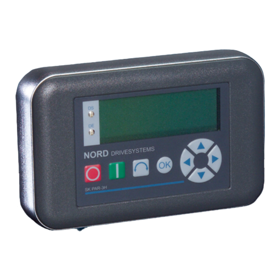
1 General information 1.1 Features 1.1.1 ParameterBox, SK PAR-2H Illuminated, high resolution LCD graphics screen • RS 485 communication interface (SK PAR-3H: RS 485 and RS 232) • Central unit for up to 5 inverters interlinked via RS 485 •... -
Page 8: Delivery
Type Version IP protection class Part Number Comments SK PAR-2E Installation IP 54 - front panel 278910110 SK PAR-2H Handheld IP 54 278910100 Incl. connection cable: M12 plug connector, length approx. 3m SK PAR-3E Installation IP 54 - front panel... -
Page 9: Parameter Boxes
2.1 Installation 2.1.1 SK PAR-2H - Handheld Version The SK PAR-2H ParameterBox is a compact control device for direct connection to the frequency inverter. A suitable connection cable with an M12 plug contact is included with the device. Direct connection of the ParameterBox to the NORDAC SK 300E and the SK 750E is possible without additional components. -
Page 10: Connection Variants
NORDAC Control and Parameter Boxes 2.1.1.2 Connection variants Subject to technical alterations BU 0040 GB-1611... -
Page 11: Par-2E - Built-In Version
2 Parameter Boxes – Installation 2.1.2 SK PAR-2E - built-in version The SK PAR-2E ParameterBox is a compact control device for control panel installation. Up to 5 frequency inverters can be connected via the internal connection terminals. Protection class IP54 is complied with on the front panel. -
Page 12: Electrical Connection
NORDAC Control and Parameter Boxes 2.1.2.2 Electrical connection WARNING Installation must be carried out by qualified personnel only, paying particular attention to safety and warning instructions. Installation or removal of modules or electrical connections must only be carried out when no voltage is present. -
Page 13: Connection To Inverter
2 Parameter Boxes – Installation 2.1.2.3 Connection to inverter A shielded signal cable should be used for the data cable between the ParameterBox and the inverter. The power supply to the ParameterBox must be between +4.5V and +30V. Please use the following connections to connect the ParameterBox with the corresponding inverter. The connections apply for fixed connection to the particular inverter via the terminal bar. -
Page 14: Simplebox Sk Csx-3H - Handheld Version
NORDAC Control and Parameter Boxes 2.1.3 SK …-3H – Handheld Version 2.1.3.1 SimpleBox SK CSX-3H – Handheld Version The SK CSX-3H SimpleBox is a compact control device for direct connection to the frequency inverter via the RJ12 diagnostic socket. A normal RJ12 -patch cable ("Modular cable RJ12 (6/6) - RJ12 (6/6), 1:1 assignment") with a length of up to 3m can be used for connection. - Page 15 2 Parameter Boxes – Installation Connection to the particular frequency inverter is made via the RJ12 connection sockets on the device. The SimpleBox SK CSX-3H can only communicate with frequency inverters. SK200E SK500E SK700E SK TI4-TU-BUS The contact assignment of the RJ-12 connection on the parameter box is as follows: Description RJ 12 P+ (A) RS 485 +...
-
Page 16: Simplebox Sk Csx-3E - Built-In Version
NORDAC Control and Parameter Boxes 2.1.4 SK …-3E - built-in version The SK CSX-3E and SK PAR3E are built-in versions of the parameter boxes described in Section 2.1.3 . If they are correctly installed in the front of the control panel they comply with protection class IP 54. 2.1.4.1 SimpleBox SK CSX-3E –... -
Page 17: Mechanical Installation In A Control Panel
2 Parameter Boxes – Installation 2.1.4.3 Mechanical installation in a control panel For installation in the control cabinet door or the control panel, a cut-out of 109mm x 64mm (tolerance +/- 1mm) must be made. The sealed unit must be inserted in the pre-processed cabinet panel. For attachment to the inside of the control panel, 6 threaded pins (M4 x 16 mm) (approx. -
Page 18: Electrical Connection Sk
NORDAC Control and Parameter Boxes 2.1.4.4 Electrical Connection SK …-3E The parameter boxes SK CSX-3E and SK PAR-3E are only connected to a frequency inverter via the RJ12 socket. This connection also provides the power supply to the box. A termination resistor (220Ω) for the RS485 bus system is integrated into the module. -
Page 19: Functions Of The Parameter Boxes
2 Parameter Boxes – Display and control 2.2 Functions of the Parameter Boxes 2.2.1 SimpleBox 2.2.1.1 Display After connection of the SimpleBox and switching on the mains voltage (or the 24V DC control voltage) of the frequency inverter, communication between the frequency inverter and the SimpleBox commences automatically. After brief illumination of all he display segments and diodes of the box a bus scan is carried out while the middle bars of the display (4-digit, 7- segment display) may flash rapidly. -
Page 20: Operation
NORDAC Control and Parameter Boxes 2.2.1.2 Operation Switching on the frequency inverter. The frequency inverter is now enabled with the set jog frequency (P113). A preset minimum frequency (P104) may at least be provided. Parameter >Interface< P509 and P510 must = 0. Switching off the frequency inverter. - Page 21 2 Parameter Boxes – Display and control Control with the SimpleBox The frequency inverter can only be controlled via the SimpleBox, if it has not previously been enabled via the control terminals or via a serial interface (P509 = 0 and P510 = 0). As well as this, with the series SK 500E and SK 700E no technology unit (SK TU3-PAR or SK TU1-PAR) may be plugged into the inverter.
- Page 22 NORDAC Control and Parameter Boxes Parameter set display P set No.. NORD DRIVESYSTEMS One menu level back or do not adopt changed value Switch from parameterisation to control SK CSX-3H (without enable (STOP)) Switch from parameterisation to control (with enable (START)) Pressed simultaneously: Select function Switching from control to...
- Page 23 2 Parameter Boxes – Display and control Menu structure with the SimpleBox Ope ra ting valu e dis play P 7 - - (o r op era tio nal) _ _ _ _ P 6 - - fo llow ing m ain s ON P 5 - - P 4 - - P 0 - -...
-
Page 24: Parameterbox
NORDAC Control and Parameter Boxes 2.2.2 ParameterBox 2.2.2.1 Display After the ParameterBox is connected and the mains voltage for the inverter is switched on, an automatic "Bus scan" is performed. The ParameterBox identifies the connected frequency inverter(s). The frequency inverter type and its current operating status can be seen in the following display. -
Page 25: Controlbox Mode
2 Parameter Boxes – Display and control 2.2.2.2 ControlBox mode Above firmware version 3.7 a further display mode (ControlBox) can be selected. If this mode is selected by the user, the displays for the ControlBox (LED display of active parameter set and 4-digit "7-segment display") are shown on the screen. -
Page 26: Operation
NORDAC Control and Parameter Boxes 2.2.2.3 Operation Graphic-capable, backlit LCD display for displaying operational values and parameters for the LCD display connected frequency inverter(s) and ParameterBox parameters. Use the Selection keys to move through the menu levels and within the individual menu items. Press the keys together to go back one level. - Page 27 2 Parameter Boxes – Display and control Control of the inverter The speed and direction of rotation of the inverter can be fully controlled via the ParameterBox. Different settings are necessary according to the inverter series. Series Parameter setting (P509) Comments SK 200E "Control terminal or keyboard"...
- Page 28 NORDAC Control and Parameter Boxes Menu structure of the ParameterBox The menu structure consists of various levels which are each arranged in a ring structure. The ENTER key moves the menu on to the next level. Simultaneous operation of the SELECTION keys moves the menu back a level. 700E 3,0kW /3 POS STD Fi/Hz 45.0...
- Page 29 2 Parameter Boxes – Display and control Parameter setup with the ParameterBox The parameterisation mode is accessed by selecting the menu item >Parameterisation< in level 1 of the ParameterBox. The parameter level of the connected inverter is accessed with the ENTER key. The following diagram illustrates the control elements of the ParameterBox for parameterisation.
- Page 30 NORDAC Control and Parameter Boxes Parameterisation in ControlBox mode Parametrisation of the frequency inverter in ControlBox mode is carried out in the same way as for parameterisation with the SimpleBox. A detailed description can be found in Section 2.2.1 under "...
-
Page 31: Data Transfer With Nord Con
The following components are required for the ParameterBox PC/laptop connection: RS232 PC / laptop USB port ParameterBox Adapter M12 So/SUB-D Interface converter Software for SK PAR-2H SK IC1 SK IC1-232/485 NORD CON SK PAR-2H Part No. 278910100 Part No. 278910210 Part No. 276970020 www.nord.com... - Page 32 NORDAC Control and Parameter Boxes PC / Laptop ParameterBox USB2.0 cable plug A to plug B Software for SK PAR-3H NORD CON SK PAR-3H Part No. 275281014 www.nord.com In this configuration, communication is controlled by the PC. For this, in the menu group >Options<, Parameter >Operating mode<...
-
Page 33: System Parameters
2 Parameter Boxes – System parameters 2.3 System parameters The following description of the system parameters only applies to ParameterBox (SK PQR.2H/ -2E/ -3H / -3E). 2.3.1 Description of parameters The menu structure of the ParameterBox is described in Section 2.2.2 "Control" under " Menu structure of the ParameterBox ". - Page 34 NORDAC Control and Parameter Boxes Parameter Setting value / Description / Note Display >ENTER< / >OK< I1 P1 Ready ONLINE P1001 P1002 P1003 P1005 P1004 Value keys Values for display Actual frequency I1 P1 Ready Value + Value - ONLINE Press selection keys simultaneously Possible actual values...
-
Page 35: Inverter Parameterisation
2 Parameter Boxes – System parameters 2.3.1.2 Inverter parameterisation Parameter Setting value / Description / Note P1101 Object selection FI1 ... FI5 and S1 … S5 Selection of the object to be parameterised. [ … ] The ongoing parameterisation process relates to the object selected. Only the devices and storage objects recognised during the bus scan are available in the selection list. -
Page 36: Options
NORDAC Control and Parameter Boxes 2.3.1.4 Options Parameter Setting value / Description / Note P1301 Language Value range: Selection of languages for operation of the ParameterBox see right hand column Available languages: German English Polish Finnish [ … ] Dutch French Italian Czech... -
Page 37: Table Of Possible Error Messages
2 Parameter Boxes – System parameters Parameter Setting value / Description / Note P1306 Box password 0 ... 9999 If the password function is to be reset, the password selected in the >Set Password< parameter must be entered here. If the correct password has been selected, than all functions of the [ 0 ] ParameterBox can be used again. - Page 38 NORDAC Control and Parameter Boxes Display Fault Cause Error number Text in the ParameterBox • Remedy Identification errors Unknown device Device ID not found. The connected inverter is not listed in the database of the ParameterBox; no communication can be established. •...
-
Page 39: Technical Data
Inverter error text A fault has occurred in the inverter with the number displayed. The inverter number error number and text are displayed. 2.4 Technical data Name SK PAR-2H SK PAR-2E SK PAR-3H SK PAR-3E SK CSX-3H SK CSX-3E Control voltage 4.5V... -
Page 40: Accessories For Nordac Parameterisation Boxes
NORDAC Control and Parameter Boxes 2.5 Accessories for NORDAC parameterisation boxes 2.5.1 SK IC1-232/485 interface converter The SK IC1-232/485 interface converter converts signals from RS485 to RS232. This converter is used for connecting a PC or a laptop to a NORDAC frequency inverter (RS485) or to a series PAR-2x ParameterBox. -
Page 41: Assignment Of Parameterisation Box - Frequency Inverter
2 Parameter Boxes – Accessories 2.5.2.2 Assignment of parameterisation box - frequency inverter ParameterBox ParameterBox SimpleBox SK CSX-3H SK PAR-2E SK PAR-2H SK PAR-3H SK PAR-3E SK CSX-3E Frequency inverter RS485 / RS485 RS485 RS485 RS485 Interface RS232 (USB) SK 200E... -
Page 42: Controlboxes
NORDAC Control and Parameter Boxes ControlBoxes With the aid of ControlBoxes it is possible to control a frequency inverter with regard to speed and direction of rotation. 3.1 SK SSX-3A – Simple Setpoint Box The "Simple Set Point Box" SK SSX-3A is a compact control unit with a 4-digit, 7-segment display, which is primarily intended for fixed connection to the terminal bar of the frequency... -
Page 43: Operating Modes
3 ControlBoxes – SK SSX-3A The connection cable must be fed out of the device via a cable gland (supplied). The cable gland must be screwed into the rear section of the housing. It is recommended that the length of the connection cable is limited to 20 m. The cable should be laid separately from other cables to avoid interference. -
Page 44: Operating Mode 485C (Control Mode Via Rs485)
NORDAC Control and Parameter Boxes 3.1.3.1 Operating mode 485C (Control mode via RS485) With the 485C operating mode, communication with the connected frequency inverter is carried out via the RS485 interfaces of the Simple Setpoint Box. Here, all the features provided by the SimpleBox SK CSX-3H/ -3E (Section 2.2) are also available. - Page 45 3 ControlBoxes – SK SSX-3A Boot UP display After switching on, the lettering briefly appears in the display Operation Control of the Simple Setpoint Box SK SSX-3A in this mode is identical to that of the SimpleBox SK CSX-3H/ -3E (see Section 2.2).
-
Page 46: Operating Mode Io-C (Control Mode Via Di1/Do1 Of The Sk 2Xxe)
NORDAC Control and Parameter Boxes 3.1.3.2 Operating mode IO-C (Control mode via DI1/DO1 of the SK 2xxE) In the operating mode IO-C, communication is via digital input "1" and digital output "1" of the frequency inverter. Here, all the features provided by the SimpleBox SK CSX-3H/ -3E (Section 2.2) are also available. Field of use In this operating mode, the box can communicate with SK 2xxE series frequency inverters with firmware version V 1.3 or higher (see parameter (P707[-01])). - Page 47 3 ControlBoxes – SK SSX-3A ATTENTION If the parameter (P434[-01]) is set to values ≠ {00} or ≠ {07}, the IO-C mode of the SK SSX-3A is barred when the frequency inverter restarts. Boot UP display After switching on, the lettering briefly appears in the display Operation Control of the Simple Setpoint Box SK SSX-3A in this mode is identical to that of the SimpleBox SK CSX-3H/ -3E (see Section 2.2).
- Page 48 NORDAC Control and Parameter Boxes Disconnection of the setpoint value channel (Connection Terminal B1 (SK SSX-3A) to Terminal 21 (SK 2xxE)) The error E009 appears in the box display after a delay. The frequency inverter does not react and maintains its operating condition.
-
Page 49: Operating Mode Io-S (Setpoint Mode Via Di1 Of The Frequency Inverter)
3 ControlBoxes – SK SSX-3A 3.1.3.3 Operating mode IO-S (Setpoint mode via DI1 of the frequency inverter) In the operating mode IO-S, communication is via digital input "1" of the frequency inverter. The frequency inverter does not return any operating or parameter values to the box. Field of use In this operating mode the box can communicate with SK 2xxE series frequency inverters. - Page 50 NORDAC Control and Parameter Boxes Boot UP display After switching on, the lettering briefly appears in the display Operation Control of the Simple Setpoint Box SK SSX-3A in this mode is the same as that of the SimpleBox SK CSX-3H/ -3E (see Section 2.2), however with the following differences: •...
- Page 51 3 ControlBoxes – SK SSX-3A function", the parameter (P400 [-07])must be parameterised to {02} "Frequency addition". In this configuration, the analog signal is processed additively to the setpoint value of the SK SSX-3A. NOTE The display on the SK SSX-3A does not provide any information about the actual speed of the drive.
-
Page 52: Technical Data
NORDAC Control and Parameter Boxes If the data connection is restored, the error must first be acknowledged (sequential pressing of the keys) in order to restart the drive. Loss of supply voltage Except for the fact that the Simple Setpoint Box switches off without an error message, the box and the frequency inverter behave identically with regard to the behaviour described above under "Disconnection of the setpoint channel". -
Page 53: Control Box (Sk Pot1-1)
3 ControlBoxes – SK POT1-1 3.2 Control box (SK POT1-1) The SK POT1-1 control box is a simple manual control unit for the control of NORDAC frequency inverters with an enabling signal and setpoint. The control box is designed for permanent connection to the frequency inverter. -
Page 54: Control Connections
NORDAC Control and Parameter Boxes Frequency inverter Option required Comments* series SK 5xxE None Up to size 4 DIP switch AIN1 (Burden resistorfor analog input 1) in setting {OFF} Above size 5 DIP switch S1 and S3 (Burden resistor foranalog input 1 and "0-10V signal processing") to setting {OFF} SK 700E... - Page 55 3 ControlBoxes – SK POT1-1 Connections are made according to the following table: Frequency inverter SK 2x0E SK 2x5E SK 300E SK 5xxE SK 700E or series SK 750E SK CU4-IOE / SK CU2-BSC / SK CU1 BSC / Interface option SK TU4-IOE SK CU2-STD SK CU1-STD /...
- Page 56 NORDAC Control and Parameter Boxes In combination with the SK CU4-24V-… or SK TU4-24V-… modules instead of the SK CU4-IOE or SK TU4-IOE Technology Units, the connection to an SK 2x5E series frequency inverter can, for example, be implemented according to the following pattern. (Note: Terminal 43 of the SK TU4-24V-…...
-
Page 57: Parameterisation
3 ControlBoxes – SK POT1-1 3.2.2 Parameterisation For the functions of the control box SK POT1-1 , some parameters must be changed, according to the frequency inverter and the options. The most important of these are listed below. For further information, please refer to the manual for the relevant frequency inverter. -
Page 58: Maintenance And Servicing Information
NORDAC Control and Parameter Boxes Maintenance and servicing information With proper use, the control and parameter boxes are maintenance-free. The device must be sent to the following address if it needs repairing: NORD Electronic DRIVESYSTEMS GmbH Tjüchkampstrasse 37 26605 Aurich, Germany For queries about repairs, please contact: Getriebebau NORD GmbH &... -
Page 59: Keyword Index
Description of parameters SK CSX-3H Dimensions 11, 17 SK IC1-232/485 6, 31, 40 DIRECTION key 20, 22, 26, 27 SK PAR-2E SK PAR-2H SK PAR-3H 14, 16 SK POT1-1 ENTER key 20, 22, 26, 27 SK SSX-3A SK TI4-TU-BUS 15, 18... - Page 60 NORDAC Control and Parameter Boxes Subject to technical alterations BU 0040 GB-1611...
Need help?
Do you have a question about the SK PAR-2H and is the answer not in the manual?
Questions and answers