Table of Contents
Advertisement
Quick Links
`
ENGLISH
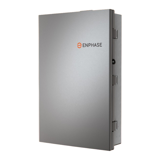
IQ System Controller 3 INT
Quick install guide
Scan the QR code for the
latest quick install guide
Scansione della Guida all'installazione
rapida più recente
Recherchez le dernier guide d'installation
rapide
Scannen voor de nieuwste
quick install guide
Procurar o Guia de Instalação Rápida mais
recente
Buscar la última Guía de instalación rápida
Σάρωση για τον πιο πρόσφατο
Οδηγό γρήγορης εγκατάστασης
Scannen Sie den QR-Code für die
neueste Schnellinstallationsanleitung
M ODE L N UMBE R:
S C 1 0 0 G - M230ROW
V E R SI O N 10.0
S E P T E MBER 2024
IQ System Controller 3 INT quick install guide
1
Advertisement
Table of Contents

Related Manuals for enphase IQ System 3 INT


Summary of Contents for enphase IQ System 3 INT
- Page 1 ENGLISH IQ System Controller 3 INT Quick install guide Scan the QR code for the latest quick install guide Scansione della Guida all’installazione rapida più recente Recherchez le dernier guide d’installation rapide Scannen voor de nieuwste quick install guide Procurar o Guia de Instalação Rápida mais recente Buscar la última Guía de instalación rápida Σάρωση...
- Page 2 All installations must comply with national and local electrical codes and standards. Only Enphase-certified installers shall install, troubleshoot, or replace the IQ System Controller 3 INT. IQ System Controller 3 INT quick install guide...
-
Page 3: Table Of Contents
Steps to de-activate System Shutdown (SSD) Switch Steps to re-activate System Shutdown (SSD) Switch IQ Gateway displays and controls Manual override mode Steps to activate the manual override Enphase Energy System shutdown procedure Maintenance Troubleshooting IQ System Controller 3 INT quick install guide... -
Page 4: Section A - Mount Iq System Controller 3 Int
As required Phillips size #2 screwdriver 2.5 mm, 3 mm, 6 mm, and 7.5 mm slotted screwdrivers 1 each * For Enphase-qualified control cable, refer to https:/ /link.enphase.com/control-cable-table-eu. For AUS/NZ the recommended control wires are Electra EAS7302PHV and LAPP 1270802. -
Page 5: What Is In The Box
Section A - Mount IQ System Controller 3 INT What is in the box S . N O I T E M N A M E Q U A N T I T Y IQ System Controller 3 INT System Shutdown (SSD) Switch Wiring kit Control (CTRL) connector (one spare, one pre-installed) Control (CTRL) connector with resistor (one spare, one pre-installed) -
Page 6: Step 1: Plan A Location For Mounting The Unit
Section A - Mount IQ System Controller 3 INT Step 1: Plan a location for mounting the unit • IQ System Controller 3 INT is IP55-rated and can be mounted both indoors and outdoors. Install the unit where it is not exposed to direct rainfall. •... -
Page 7: Step 2: Minimum Clearance
Section A - Mount IQ System Controller 3 INT Step 2: Minimum clearance This product must be installed with clearances, as shown in the figure. Follow all local standards and regulations related to mounting an electrical distribution panel. If using side power cable/Ethernet cable entry, pre-drill conduit holes before installing. NOTE: Clearances indicated are after the installation. -
Page 8: Step 3: Open The Door
Section A - Mount IQ System Controller 3 INT Step 3: Open the door WARNING: Risk of injury and equipment damage. Avoid Install the IQ System Controller 3 INT as per the instructions below. dropping the IQ System Controller 3 INT. Doing so may Please note the following before installing: create a hazard, cause serious injury, and/or damage the •... -
Page 9: Step 4: Mount The Iq System Controller 3 Int
Section A - Mount IQ System Controller 3 INT Step 4: Mount the IQ System Controller 3 INT WARNING: Risk of electric shock. To maintain the warranty, do not modify the dead front other than to remove or replace filler plates as needed. -
Page 10: Step 5: Drill Cable Entry Holes
Section A - Mount IQ System Controller 3 INT Step 5: Drill cable entry holes Drill conduit entry/cable gland holes as needed and install conduit WARNING: Do not drill the conduit holes once the unit is grounding lugs or cable glands in each opening before mounting mounted on the wall. -
Page 11: Step 6: Open The Dead Front
Section A - Mount IQ System Controller 3 INT Step 6: Open the dead front Before removing the dead front, ensure the IQ System Controller 3 INT is completely de-energized. WARNING: Risk of equipment damage and electrocution. Do not wire the IQ System Controller 3 INT when it is energized. Phillips screw #2 Torque: 1.4 N m Dead front... -
Page 12: Section B - Wiring
Section B - Wiring Internal view of IQ System Controller 3 INT IQ System Controller 3 INT with the dead front removed is shown in the image below. DIN rails are provided to install circuit breakers. Use conductors (line, neutral, and ground/earth) and circuit breakers of suitable current rating and protection requirements according to local codes. -
Page 13: Power Terminal Details
Section B - Wiring Power terminal details PV terminals PV neutral terminal IQ Battery terminals DER termination label Grid/Mains terminals Main relay label Non-backup load terminals Earth bar Backup load terminals Neutral bar/Battery neutral terminal WARNING: Ensure that the phase conductors are connected to their respective terminals. The sequence of phase terminals in the unit is L3-L2-L1 from left to right. -
Page 14: Wiring Scenarios
Section B - Wiring Wiring scenarios N E U T R A L G R I D N E U T R A L A P P L I C A B L E C I R C U I T C O M PAT I B L E B AT T E R Y W I R I N G S C E N A R I O W I R I N G S C E N A R I O S... -
Page 15: Additional Wiring Instructions
Section B - Wiring Additional wiring instructions Supported earthing systems: The supported earthing systems are TN-C-S, TN-S, and TT. WARNING: Ensure that the phase conductors are connected The earthing systems that are not supported are TN-C and IT. to their respective terminals. The sequence of phase terminals in the unit is L3-L2-L1 from left to right. -
Page 16: Wiring Sequence: Three-Phase
Section B - Wiring Wiring sequence: Three-phase WARNING: Ensure that the phase conductors are connected to their respective terminals. The sequence of phase terminals in the unit is L3-L2-L1 from left to right. IQ System Controller 3 INT quick install guide... -
Page 17: Wire Control (Ctrl) Cable To Headers
(with the same numerals as NOTE: Use Enphase-recommended cables and headers, and on the headers). This will enable easy identification of wires refer to local codes for any specific local requirements. -
Page 18: Control (Ctrl) Wiring Between System Components
Section B - Wiring Control (CTRL) wiring between system components Control wiring guidance for the Enphase Energy System: • One header with a termination resistor should be installed Refer to the following wiring sequences to understand the position on each component at the end of the control network. -
Page 19: Drain Wire Termination
Section B - Wiring Sequence 3: IQ Battery(s) 5P → IQ System Controller 3 INT → IQ Battery(s) 5P IQ Battery 5P IQ System Controller 3 INT IQ Battery 5P CTRL cable Drain wire Termination resistor NOTE: The total length of CTRL wiring across the system should not exceed 100 meters to ensure optimal system performance. -
Page 20: System Shutdown (Ssd) Switch Wiring
Secure the switch to the rear plate of the enclosure using maintenance technicians. When the system shutdown sequence push-fit latches. outlined in this section is followed, the Enphase Energy System will be shut down, and the home will be connected to the grid. •... -
Page 21: Aux Wiring
IO1 and IO2 act as NC1 and NC2. IO3 and IO4 act as NO1 and NO2. Functionalities of the aux contacts can be configured using the Enphase Installer App as shown below. IQ System Controller 3 INT quick install guide... -
Page 22: Aux Wiring: Pv Shedding/Load Control
Section B - Wiring AUX wiring: PV shedding/load control PV shedding Load control PV shedding allows oversized PV systems with IQ7 and S Series In off-grid state low-priority loads with high power requirements Microinverters to be installed with grid-forming batteries and may deplete energy storage. -
Page 23: Close The Dead Front And Install The Breaker Filler Plate
Close the dead front and install the breaker filler plate WARNING: Before energizing, make sure that all IQ System Controller 3 INT connections are properly installed, and conductors terminated. • Reattach the dead front using the three screws and tighten them using a Phillips screwdriver #2. -
Page 24: Mobile Connect Cellular Modem
Mobile Connect cellular modem NOTE: The cellular connection is only intended as a backup communication channel. Primary internet connectivity must be provided using the homeowner’s Ethernet/Wi-Fi. Cellular connectivity is subject to network operator coverage and signal strength. The IQ System Controller 3 INT is packaged with the Mobile Connect Cellular modem - CELLMODEM-M1-06-AT-05 or CELLMODEM-07-INT-05. -
Page 25: Final Checks And System Commissioning
If you do not see the IQ System Controller 3 INT DANGER: Risk of electric shock. The terminals of IQ System information in the Enphase Installer App, check that the Controller 3 INT are exposed and can be energized if any of IQ Gateway AP mode light is green. -
Page 26: Operation
Ensure that the unit is connected to the internet and clear of debris or moisture. Track system installation progress with the Enphase Installer App. The LEDs on the IQ Gateway PCB (printed circuit board) are solid green when a function is enabled or performing as To clean the external surfaces of the unit, use a soft cloth. -
Page 27: Iq System Controller 3 Int Leds
IQ System Controller 3 INT LEDs IQ Gateway LEDs LED 1 L E D C O L O U R S TAT E D E S C R I P T I O N Not operating Flashing green Switched on; booting Solid green Operational Flashing red... -
Page 28: Iq Gateway Leds And Buttons
E V E N T Flashing green Connecting to EIP or the Wi-Fi router. Green IQG is connected to the Enphase Installer Platform (EIP). Connected to the local network only, i.e., without internet. No network is available. AP MODE LED... -
Page 29: Cellular Modem Status Leds
IQ Gateway Network communications LED is solid green. You DC power via USB not present can use the Enphase Installer App to check the modem status and cellular signal strength. The IQ Gateway’s AP (Access Point) Wi-Fi DC power via USB present network allows you to connect your mobile device (smartphone or tablet) to the IQ Gateway. -
Page 30: Safety
• Away from excessive dust, corrosive and explosive gases, and oil smoke DANGER: Risk of electric shock. Do not use Enphase equipment in a manner not • Away from direct exposure to gas exhaust, such as from motor specified by the manufacturer. Doing so may cause death or injury to persons or vehicles damage to equipment. -
Page 31: Precautions For Pacemaker Wearers
IQ System Controller 3 INT and IQ Battery 5P units. Further, Enphase reserves the right to refuse to provide Territory. The Cellular modem shall only be used in the countries listed on this support in connection with any such use and disclaims any and all liability quick installation guide (QIG). - Page 32 Wiring scenarios N E U T R A L G R I D N E U T R A L A P P L I C A B L E C I R C U I T C O M PAT I B L E B AT T E R Y W I R I N G S C E N A R I O W I R I N G S C E N A R I O S D I S C O N N E C T I O N I N...
-
Page 33: Appendix A - Wiring Scenarios
Appendix A - Wiring scenarios Applicable regions: Australia New Zealand Single-phase home NOTE: A1: System with single-phase IQ Battery The grid neutral will not be disconnected in backup and PV without neutral disconnection. mode. If there are no separate backup or non-backup panels, then wire only one neutral wire from the mains panel or as per local regulation. -
Page 34: A2: System With Single-Phase Iq Battery And
Appendix A - Wiring scenarios Applicable region: South Africa Single-phase home A2: System with single-phase NOTE: If local regulations require the use of an RCD, then IQ Battery IQ Battery and PV with neutral and PV require separate RCDs. In the case of the use of a disconnection and neutral breakers. -
Page 35: A3: System With Single-Phase Iq Battery And
Appendix A - Wiring scenarios Applicable regions: France Netherlands Belgium Single-phase home New Caledonia A3: System with single-phase IQ Battery NOTE: An RCBO can be used in place of an RCD and MCB for and PV with neutral disconnection PV and IQ Battery circuits. When using an RCBO, and neutral circuit breakers. -
Page 36: Neutral Disconnection
Appendix A - Wiring scenarios Applicable region: Australia Three-phase home NOTE: In Australia and New Zealand, the grid neutral will not A4: Grid/mains and loads without be disconnected. If there are no separate backup or non-backup neutral circuit breaker and panels, then wire only one neutral conductor from the without neutral disconnection. -
Page 37: A5: Three-Phase Pv And Single-Phase Iq Battery On L1
Appendix A - Wiring scenarios Applicable region: Australia Three-phase home A5: Three-phase PV and NOTE: For three-phase homes, do not daisy chain neutral single-phase IQ Battery on L1 wire across batteries on different phases. Each phase of batteries must have a separate neutral wire that is terminated on the neutral bar in IQ System Controller 3 INT. -
Page 38: Switching
Appendix A - Wiring scenarios Applicable region: South Africa Three-phase home A6: Grid/mains and loads with neutral circuit breaker and neutral switching. Grid/Mains terminals Non-backup loads terminals Backup loads terminals Earth bar Neutral bar/Terminal for battery neutral connection Non-backup circuit breaker Backup circuit breaker IQ Gateway circuit breaker (pre-installed and pre-wired) -
Page 39: A7: Three-Phase Pv And Single-Phase Iq Battery On L1
Appendix A - Wiring scenarios Applicable region: South Africa Three-phase home A7: Three-phase PV and NOTE: For three-phase homes, do not daisy chain neutral single-phase IQ Battery on L1 wire across batteries on different phases. Each phase of batteries must have a separate neutral wire that is terminated on the neutral bar in IQ System Controller 3 INT. -
Page 40: Neutral Switching
Appendix A - Wiring scenarios Applicable region: Germany Three-phase home A8: Grid/mains and loads without neutral circuit breaker and with neutral switching. Grid/Mains terminals Non-backup loads terminals Backup loads terminals Earth bar Neutral bar/Terminal for battery neutral connection Non-backup circuit breaker Backup circuit breaker IQ Gateway circuit breaker (pre-installed and pre-wired) -
Page 41: A9: Three-Phase Pv And Iq Battery
Appendix A - Wiring scenarios Applicable region: Germany Three-phase home A9: Three-phase PV and NOTE: An RCBO can be used in place of an RCD and IQ Battery. MCB for PV and IQ Battery circuits. When using an RCBO, IQ Battery and PV require separate RCBO. -
Page 42: Neutral Switching
Appendix A - Wiring scenarios Applicable regions: Austria Switzerland Three-phase home A10: Grid/mains and loads without neutral NOTE: circuit breaker and with neutral switching. Local regulations in Austria may require that an RCD be installed on the backup circuit. Grid/Mains terminals Non-backup loads terminals Backup loads terminals Earth bar... -
Page 43: A11: Three-Phase Pv And Iq Battery
Appendix A - Wiring scenarios Applicable regions: Austria Switzerland Three-phase home A11: Three-phase PV and IQ Battery. NOTE: An RCBO can be used in place of an RCD and MCB for PV and IQ Battery circuits. When using an RCBO, IQ Battery and PV require separate RCBO. -
Page 44: Revision History
Revision history R E V I S I O N D AT E D E S C R I P T I O N 140-00273-10 September 2024 Added three-phase wiring sequence warning labels. 140-00273-09 August 2024 Updated the wiring pages for Australia and New Zealand. Added the “Installer checklist”... -
Page 45: Installer Notes
Installer notes IQ System Controller 3 INT quick install guide... - Page 46 Installer notes IQ System Controller 3 INT quick install guide...
-
Page 47: Installer Checklist
Installer checklist Checklist to be used before powering up the system(follow the local regulation): ☒ A local earth electrode is present and functional ☒ IQ System Controller is clean and free of any debris. ☒ Grid supply is wired from the mains switchboard/grids supply to the grid/mains terminals in the IQ System Controller. ☒... - Page 48 IQSC-3-QIG-00273-10-EN-INT-2024-09-17 © 2024 Enphase Energy. All rights reserved. Enphase, the e and CC logos, IQ, and certain other marks listed at https:/ /enphase.com/trademark-usage-guidelines are trademarks of Enphase Energy, Inc. in the U.S. and other countries. Data subject to change. IQ System Controller 3 INT quick install guide...
Need help?
Do you have a question about the IQ System 3 INT and is the answer not in the manual?
Questions and answers