Table of Contents
Advertisement
Advertisement
Table of Contents

Related Manuals for MSI 5000P Master-A4M


Summary of Contents for MSI 5000P Master-A4M
- Page 1 5000P Master MS-9175 (V1.X) Server Board G52-91751X1...
-
Page 2: Trademarks
Alternatively, please try the following help resources for further guidance. Visit the MSI website at http://www.msi.com.tw/program/service/faq/ faq/esc_faq_list.php for FAQ, technical guide, BIOS updates, driver updates, and other information. Contact our technical staff at http://support.msi.com.tw/. -
Page 3: Safety Instructions
Safety Instructions Always read the safety instructions carefully. Keep this User’s Manual for future reference. Keep this equipment away from humidity. Lay this equipment on a reliable flat surface before setting it up. The openings on the enclosure are for air convection hence protects the equip- ment from overheating. -
Page 4: Fcc-B Radio Frequency Interference Statement
FCC-B Radio Frequency Interference Statement T h is eq uip men t h as been tested and found to c omply with the limits for a Class B digital device, pursuant to Part 15 of the FCC Rules. These limits are designed to provide reasonable protection against harmful interference in a residential installation. -
Page 5: Weee (Waste Electrical And Electronic Equipment) Statement
WEEE (Waste Electrical and Electronic Equipment) Statement... -
Page 8: Table Of Contents
CONTENTS Copyright Notice ......................ii Trademarks ........................ii Revision History ......................ii Technical Support ......................ii Safety Instructions ......................iii FCC-B Radio Frequency Interference Statement ............iv W EEE (Waste Electrical and Electronic Equipment) Statement ........v Chapter 1 Getting Started ..................1-1 Mainboard Specifications ................... - Page 9 BIOS Recovery Jumper: J5 ..............2-16 Clear BIOS Password Jumper: J7 ............2-16 Slots ........................2-17 PCI (Peripheral Component Interconnect) Express Slots ....... 2-17 PCI (Peripheral Component Interconnect) Slots ........2-17 PCI Interrupt Request Routing ..............2-17 Chapter 3 BIOS Setup ..................... 3-1 Entering Setup .....................
- Page 10 2.3 IM/IME Description ................. B-5 2.4 Integrated Mirroring Firmware ............B-7 2.5 Fusion-MPT Support ................B-8 3. Creating Integrated Mirroring Volumes ............B-8 3.1 IM Configuration Overview ..............B-9 3.2 Creating IM and IME Volumes .............. B-9 3.3 Creating a Second IM or IME Volume ..........B-12 3.4 Managing Hot Spares ................
-
Page 11: Chapter 1 Getting Started
Getting Started Chapter 1 Getting Started Thank you for choosing the 5000P Master (MS-9175 v1.X), an excellent E-ATX server board from MSI. ® Based on the innovative Intel 5000P & ESB2 control- lers for optimal system efficiency, the 5000P Master ®... -
Page 12: Mainboard Specifications
MS-9175 Server Board Mainboard Specifications Processor Support ® - Intel Dual-Core Xeon (Dempsey, W oodcrest) in Socket LGA771 (Quad-Core support by optional SKU) - Supports 3/4 pin CPU Fan Pin-Header with Fan Speed Control Supported FSB - 1066/ 1333 MHz Chipset ®... - Page 13 - W ake up on USB @ S1 only - Wake up on PCI (PME) - ACPI S1, S4 and S5 functions Form Factor - E-ATX form factor: 12.0 X 13.0 inch M ounting - 9 mounting holes For more information on compatible components, please visit http://www.msi.com.tw/program/products/server/svr/pro_svr_qvl.php...
-
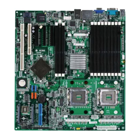
Page 14: Mainboard Layout
MS-9175 Server Board Mainboard Layout J FAN1 JFAN 5 J FAN 2 T: Mouse B:Keyboard D IMM3 3 D IMM3 2 D IMM3 1 D IMM2 3 D IMM2 2 D IMM2 1 D IMM1 3 D IMM1 2 D IMM11 LAN jack Intel Blackford... -
Page 15: Chapter 2 Hardware Setup
Hardware Setup Chapter 2 Hardware Setup This chapter provides you with the information about hardware setup procedures. While doing the installation, be careful in holding the components and follow the installation procedures. For some components, if you install in the wrong orientation, the components will not work properly. -
Page 16: Quick Components Guide
MS-9175 Server Board Quick Components Guide JFAN6, DDRII DIMMs, CPU, p.2-3 JPWR2, p.2-13 p.2-6 p.2-9 JFAN1/2/5 , JPWR3, JFAN4 , p.2-13 p.2-9 p.2-13 JPWR1, p.2-9 Back Panel I/O, p.2-8 CN1, p.2-13 JUSB1/2, p.2-15 COM2, p.2-13 JFAN6, p.2-13 JRST, PCI Slots, p.2-14 p.2-18 JSSI1,... -
Page 17: Cpu (Central Processing Unit)
CPU has a heat sink and a cooling fan attached on the top to prevent overheating. If you do not have the heat sink and cooling fan, contact your dealer to purchase and install them before turning on the computer. For more information on compatible components, please visit http://www.msi.com. tw/program/products/server/svr/pro_svr_qvl.php . Important 1. -
Page 18: Cpu, Heatsink, And Heat Pipe Cooler
MS-9175 Server Board CPU, Heatsink, and Heat Pipe Cooler 1. Locate the CPU socket. 2. Raise the load lever up to its full extent. 3. Open the load plate. 4. After confirming the CPU direction (indicated below with red circles) for correct mating, put down the CPU in the socket housing frame. -
Page 19: Installing The Intel Cpu Cooler
Hardware Setup Installing the Intel CPU Cooler 1. Flip over the mainboard and locate the position of the CPU sockets. 2. Install the backplates to the back of the CPU sockets with holes aligned. CPU cooler backplate 3. Install the CPU(s) following the in- 5. -
Page 20: Memory
MS-9175 Server Board Memory The mainboard provides twelve 240-pin ECC DDRII 533/667 FBD DIMM slots and supports up to 48 GB system memory. For more information on compatible components, please visit http://www.msi.com. tw/program/products/server/svr/pro_svr_qvl.php. DDRII 240-pin, 1.8V 68x2=1363 pin 52x2=104 pin Memory Population Rules This mainboard supports DDRII FBD 533/667 memory interface. -
Page 21: Installing Ddrii Modules
Hardware Setup Installing DDRII Modules 1. The memory module has only one notch on the center and will only fit in the right orientation. 2. Insert the memory module vertically into the DIMM slot. Then push it in until the golden finger on the memory module is deeply inserted in the DIMM slot. -
Page 22: Back Panel
MS-9175 Server Board Back Panel LAN Port M ou se Gb LAN Ports Serial Port VGA Port USB Ports Keyboard M ouse/Keyboard Connector ® ® The standard PS/2 mouse/keyboard DIN connector is for a PS/2 mouse/keyboard. Serial Port Connector The serial port is a 16550A high speed communications port that sends/ receives 16 bytes FIFOs. -
Page 23: Power Supply
Hardware Setup Power Supply SSI 24-Pin System Power Connector: JPWR1 This connector allows you to connect to an SSI power supply. To connect to the SSI power supply, make sure the plug of the power supply is inserted in the proper orientation and the pins are aligned. -
Page 24: Connectors
MS-9175 Server Board Connectors ATA100 Hard Disk Connector: IDE1 The mainboard has a 32-bit Enhanced PCI IDE and Ultra DMA 66/100 controller that provides PIO mode 0~4, Bus Master, and Ultra DMA 66/100 function. You can connect hard disk drives, CD-ROM and other IDE devices. The Ultra ATA100 interface boosts data transfer rates between the computer and the hard drive up to 100 megabytes (MB) per second. -
Page 25: Serial Ata Connectors: Sata1~Sata4
Hardware Setup Serial ATA Connectors: SATA1~SATA4 SATA1~SATA4 are high-speed SATA interface ports and support SATA data rates of 300MB/s. Each SATA II connector can connect to 1 hard disk device. SATA1 SATA3 SATA2 SATA4 Serial ATA cable Take out the dust cover and connect to the hard disk devices Connect to SATA1/2/3/4... -
Page 26: Serial Attached Scsi Connectors: Sas1/ Sas2
MS-9175 Server Board Serial Attached SCSI Connectors: SAS1/ SAS2 The SAS connector is a new generation serial communication protocol for devices designed to allow for much higher speed data transfers. It supports data transfer speeds up to 3 Gbit/s. SAS uses serial communication instead of the parallel method found in traditional SCSI devices but still uses SCSI commands for interacting with SAS devices. -
Page 27: Fan Power Connectors: Jfan1/ 2/ 3/ 4/ 5/ 6
Hardware Setup Fan Power Connectors: JFAN1/ 2/ 3/ 4/ 5/ 6 The fan power connectors support system cooling fan with +12V. W hen connecting the wire to the connectors, always take note that the red wire is the positive and should be connected to the +12V, the black wire is Ground and should be connected to GND. -
Page 28: Front Panel Connector: Jssi1
MS-9175 Server Board Front Panel Connector: JSSI1 The mainboard provides one front panel connector for electrical connection to the front panel switches and LEDs. Chassis Giga-bit Intruder Standby LAN1 LED Giga-bit Power (5V) SMBus LAN2 LED JSSI1 Power Power LED Switch Reset Switch JSSI1 Pin Definition... -
Page 29: Front Usb Connectors: Jusb1, Jusb2
Hardware Setup Front USB Connectors: JUSB1, JUSB2 The mainboard provides two USB 2.0 pinheaders (optional USB 2.0 bracket available) ® that are compliant with Intel I/O Connectivity Design Guide. USB 2.0 technology increases data transfer rate up to a maximum throughput of 480Mbps, which is 40 times faster than USB 1.1, and is ideal for connecting high-speed USB interface peripherals such as USB HDD, digital cameras, M P3 players, printers, mo- dems and the like. -
Page 30: Jumpers
MS-9175 Server Board Jumpers Clear CMOS Jumper: JBAT1 There is a CMOS RAM onboard that has a power supply from external battery to keep the data of system configuration. With the CMOS RAM, the system can automatically boot OS every time it is turned on. If you want to clear the system configuration, set the JBAT1 (Clear CMOS Jumper ) to clear data. -
Page 31: Slots
Hardware Setup Slots PCI (Peripheral Component Interconnect) Express Slots PCI Express architecture provides a high performance I/O infrastructure for Desktop Platforms with transfer rates starting at 2.5 Giga transfers per second over a PCI Express x1 lane for Gigabit Ethernet, TV Tuners, 1394 controllers, and general pur- pose I/O. -
Page 32: Chapter 3 Bios Setup
BIOS Setup Chapter 3 BIOS Setup This chapter provides information on the BIOS Setup program and allows you to configure the system for optimum use. You may need to run the Setup program when: ² An error message appears on the screen during the system booting up, and requests you to run SETUP. -
Page 33: Entering Setup
MS-9175 Server Board Entering Setup Power on the computer and the system will start POST (Power On Self Test) process. W hen the message below appears on the screen, press <F2> key to enter Setup. Press F2 to enter SETUP If the message disappears before you respond and you still wish to enter Setup, restart the system by turning it OFF and On or pressing the RESET button. -
Page 34: Control Keys
BIOS Setup Control Keys < > Move to the previous item < > Move to the next item < > Move to the item in the left hand < > Move to the item in the right hand <Enter> Select the item <Esc>... -
Page 35: The Menu Bar
MS-9175 Server Board The Menu Bar Main Use this menu for basic system configurations, such as time, date etc. Advanced Use this menu to set up the items of special enhanced features available on your system’s chipset. Security Use this menu to set Supervisor and User Passwords. Power Use this menu to specify your settings for power management. - Page 36 BIOS Setup Main System Time The time format is <Hour> <Minute> <Second>. System Date The date format is <Month> <Date> <Year>. IDE Channel 0/Secondary Master/Slave [Type] Press PgUp/<+> or PgDn/<-> to select [Manual], [None] or [Auto] type. Note that the specifications of your drive must match with the drive table.
- Page 37 MS-9175 Server Board Boot Features Press <Enter> to enter the sub-menu and the following screen appears: Boot-Time Diagnostic Screen Setting the option to [Enabled] allows the system to display the diagnostic screen during boot. QuickBoot M ode Setting the item to [Enabled] allows the system to boot within 5 seconds since it will skip some check items.
-
Page 38: Advanced
BIOS Setup Advanced Advanced Chipset Control Press <Enter> to enter the sub-menu and the following screen appears: SERR Signal Condition [None] Disables assertion of SERR# on memory error [Single bit] Enables SERR# assertion on single-bit memory errors... - Page 39 MS-9175 Server Board [Multiple bit] Enables SERR# assertion on multi-bit memory errors [Both] Enables SERR# assertion on both single and multi-bit memory errors M emory Branch Mode [Interleave] This function can write data interleaved between multiple of memories. It can increase the speed of memory writing. [Mirror] This function can write duplicate data onto a pair of memories.
- Page 40 BIOS Setup Advanced Processor Options Press <Enter> to enter the sub-menu and the following screen appears: Intel Virtualization Technology Virtualization enhanced by Intel Virtualization Technology will allow a platform to run multiple operating systems and applications in independent partitions. With virtualization, one computer system can function as multiple “virtual” systems.
- Page 41 MS-9175 Server Board I/O Control Sub-Menu Press <Enter> to enter the sub-menu and the following screen appears: Intel I/O AT Function This field enables Intel I/O Acceleration Technology which can move data more efficiently. COM Ports Setting Press <Enter> to enter the sub-menu and the following screen appears: Serial Port A/B These field allows you to the onboard Serial Port A/B.
- Page 42 BIOS Setup Base I/O Address These items specify the base I/O addresses of the onboard Serial Port A/B. Interrupt These field allows you to select IRQ Resources for Serial Port A/B. Parallel ATA A This setting allows you to enable or disable the onchip Parallel-ATA controller. Serial ATA A This setting allows you to enable or disable the onchip Serial-ATA controller.
- Page 43 MS-9175 Server Board Server M anagement Sub-M enu Press <Enter> to enter the sub-menu and the following screen appears: DM I Event Logging Press <Enter> to enter the sub-menu and the following screen appears: Event log validity/capacity These items indicate the status of Event log validity and capacity. View DMI event log These item allows you to view the content of the DMI event log.
- Page 44 BIOS Setup ECC Event Logging This function is used to log ECC events. Clear all DM I event logs This function is used to clear all DMI event logs. IPMI Press <Enter> to enter the sub-menu and the following screen appears: IPMI Specification Version Indicate the IPMI (Intelligent Platform Management Interface) version.
- Page 45 MS-9175 Server Board BIOS POST Errors These field allows you to log POST Errors. BIOS POST Watchdog Setting the option to [Enabled] If BIOS POST fails, W atchdog restarts the BIOS POST. OS boot Watchdog Setting the option to [Enabled] If OS boot fails, Watchdog Timer reboots the Timer for loading OS (min) This setting specifies the timer for loading OS.
-
Page 46: Security
BIOS Setup Security Supervisor Password Is, User Password Is These items indicate the status of password settings. Set Supervisor Password Supervisor Password controls access to the BIOS Setup utility. Set User Password User Password controls access to the system at boot. Password On Boot Choosing [Enabled] requires a password on boot. - Page 47 MS-9175 Server Board Power Wake On LAN The item specifies how the system will be awakened from power saving mode when input signal of the LAN is detected. Resume On Time Select [On] to wake up the system at predetermined time. Resume Time The time format is <HH>...
-
Page 48: Boot
BIOS Setup Boot These settings allow users to set the priority of the specified devices.You may use the arrow keys ( ) to select the desired device, <+>/<-> key to move it up/down in the priority list, <f>/<r> key to specify the device fixed or removable, <x> key to exclude or include the device to boot, (Shift + 1) to enable or disable a device, (1 - 4) keys to load default boot sequence. -
Page 49: Exit
MS-9175 Server Board Exit Exit Saving Changes Save changes to CMOS and exit setup. Exit Discarding Changes Abandon all changes and exit setup. Load Setup Defaults Use this menu to load the default values set by the BIOS vendor for stable system performance. -
Page 50: Appendix A Intel Sata Raid
Intel SATA RAID Appendix A Intel SATA RAID The Southbridge provides a hybrid solution that com- bines four independent SATAII ports for support of up to four Serial ATAII (Serial ATAII RAID) drives. It offers RAID level 0 (Striping), RAID level 1 (Mirroring and Duplexing), RAID level 5 (Block Interleaved Distrib- uted Parity), RAID level 10 (A Stripe of Mirrors) and ®... -
Page 51: Introduction
MS-9175 Server Board Introduction The Southbridge provides a hybrid solution that combines four independent SATAII ports for support of up to four Serial ATAII (Serial ATAII RAID) drives. Serial ATAII (SATAII) is the latest generation of the ATA interface. SATA hard drives deliver blistering transfer speeds up to 300MB/sec. -
Page 52: Bios Configuration
Intel SATA RAID BIOS Configuration The Intel Matrix Storage Manager Option ROM should be integrated with the system BIOS on all motherboards with a supported Intel chipset. The Intel Matrix Stroage Manager Option ROM is the Intel RAID implementation and provides BIOS and DOS disk services. - Page 53 MS-9175 Server Board After pressing the <Ctrl> and <I> keys simultaneously, the following window will appear: (1) Create RAID Volume Select option 1 “Create RAID Volume” and press <Enter> key. The following screen appears. Then in the Name field, specify a RAID Volume name and then press the <TAB>...
- Page 54 Intel SATA RAID In the Disk field, press <Enter> key and the following screen appears. Use <Space> key to select the disks you want to create for the RAID volume, then click <Enter> key to finish selection. Then select the strip value for the RAID array by using the “upper arrow” or “down arrow”...
- Page 55 MS-9175 Server Board Important Since you want to create two volumes (Intel Matrix RAID Technology), this default size (maximum) needs to be reduced. Type in a new size for the first volume. As an example: if you want the first volume to span the first half of the two disks, re-type the size to be half of what is shown by default.
- Page 56 Intel SATA RAID (2) Delete RAID Volume Here you can delete the RAID volume, but please be noted that all data on RAID drives will be lost. Important If your system currently boots to RAID and you delete the RAID volume in the Intel RAID Option ROM, your system will become unbootable.
- Page 57 MS-9175 Server Board (3) Reset Disks to Non-RAID Select option 3 Reset Disks to Non-RAID and press <Enter> to delete the RAID volume and remove any RAID structures from the drives. The following screen appears: Press <Y> key to accept the selection. Important 1.
-
Page 58: Installing Software
Windows XP/2000 installation. † Existing Windows XP/2000 Driver Installation 1. Insert the MSI CD into the CD-ROM drive. 2. The CD will auto-run and the setup screen will appear. 3. Under the Driver tab, click on Intel IAA RAID Edition. -
Page 59: Installation Of Intel Matrix Storage Console
For this reason, you cannot remove or un-install this driver from the system after installation; however, you will have the ability to un-install all other non-driver components. Insert the MSI CD and click on the Intel IAA RAID Edition to install the software. Click on this item A-10... - Page 60 Intel SATA RAID The InstallShield Wizard will begin automatically for installation showed as following: Click on the Next button to proceed the installation in the welcoming window. A-11...
- Page 61 MS-9175 Server Board The window shows the components to be installed. Click Next button to continue. After reading the license agreement in the following window, click Yes button to continue. A-12...
- Page 62 Intel SATA RAID Select the folder in which you want the program to be installed in the following window, and click Next button to start installation. Select a program folder in the following window where you want Setup to add the program icon.
- Page 63 MS-9175 Server Board The following window appears to show the Intel Application Accelerator RAID Edition Setup installation status. Once the installation is complete, the following window appears. A-14...
-
Page 64: Raid Migration Instructions
Intel SATA RAID RAID Migration Instructions The Intel Matrix Storage Console offers the flexibility to upgrade from a single Serial ATA (SATA) hard drive to RAID configuration when an additional SATA hard drive is added to the system. This process will create a new RAID volume from an existing disk. -
Page 65: Create Raid Volume From Existing Disk
MS-9175 Server Board Create RAID Volume from Existing Disk To create a RAID volume from an existing disk, choose Action --> Create RAID Volume from Existing Hard Drive. The Create RAID Volume from Existing Hard Drive Wizard pops up to lead you for the following procedure. - Page 66 Intel SATA RAID (1) Step 1: Configure Volume Here you can configure the new RAID volume by entering the volume name, selecting the RAID level and strip size. † RAID Volume Name: A desired RAID volume name needs to be typed in where the ‘RAID_Volume1’ text currently appears above.
- Page 67 MS-9175 Server Board expensive (requiring read-in prior to write, in order to be able to calculate the correct parity information), or similar to RAID-1 writes. The write efficiency depends heavily on the amount of memory in the machine, and the usage pattern of the array. Heavily scattered writes are bound to be more expensive.
- Page 68 Intel SATA RAID (3) Select Member Hard Drive(s) Then select the member disk (the target disk) that you wish to use and then click “- -->” to move it to the Selected field. Then click Next to continue. Please note that the existing data on the selected hard drive(s) will be deleted permanently.
- Page 69 MS-9175 Server Board (4) Specify Volume Size Specify the amount of available array space to be used by the new RAID volume. You may enter the amount in the space or use the slider to specify. It is recommended you use 100% of the available space for the optimized usage.
- Page 70 Intel SATA RAID (6) Start Migration The migration process may take up to two hours to complete depending on the size of the disks being used and the strip size selected. A dialogue window will appear stating that the migration process may take considerable time to complete, meanwhile a popup dialogue at the taskbar will also show the migration status.
-
Page 71: Missing Hard Drive Member
MS-9175 Server Board Degraded RAID Array A RAID 1, RAID 5 or RAID 10 volume is reported as degraded when one of its hard drive members fails or is temporarily disconnected, and data mirroring is lost. As a result, the system can only utilize theremaining functional hard drive member. To re- establish data mirroring and restore data redundancy, refer to the procedure below that corresponds to the current situation. - Page 72 Intel SATA RAID 5. Exit Intel RAID Option ROM, and then reboot to W indows system. 6. W hen prompted to rebuild the RAID volume, click 'Yes'. 7. The Intel(R) Storage Utility will be launched. Right-click the new hard drive and select 'Rebuild to this Disk'.
-
Page 73: Appendix Blsi Sas Raid
LSI SAS RAID Appendix B LSI SAS RAID This appendix explains how to configure and use the components of the LSI Logic Integrated RAID (IR) soft- ware with LSI SAS 106 4/1 064E & 1068 /106 8E controllers. -
Page 74: Introduction To Integrated Raid
MS-9175 Server Board 1. Introduction to Integrated RAID This section provides an overview of the LSI Logic Integrated RAID solution for LSI Logic SAS controllers, its features, and its benefits. The LSI Logic Integrated RAID solution provides cost benefits for the server or workstation market where the extra performance, storage capacity, and/or redun- dancy of a RAID configuration are required. -
Page 75: Integrated Mirroring Overview
LSI SAS RAID 2. Integrated Mirroring Overview This section provides an overview of the LSI Logic Integrated Mirroring (IM) feature. 2.1 Introduction As a result of the shift towards Network Attached Storage (NAS), ISPs need a cost effective, fault-tolerant solution to protect the operating systems on small form factor, high-density, rack-mountable servers. -
Page 76: Im Features
MS-9175 Server Board 2.2 IM Features LSI Logic Integrated Mirroring and Integrated Mirroring Enhanced support the follow- ing features: Configurations of one or two IM or IME volumes on the same LSI Logic SAS controller. Each volume can consist of two mirrored disks (IM) or three to eight mirrored disks (IME). -
Page 77: Im/Ime Description
LSI SAS RAID 2.3 IM/IME Description The LSI Logic Integrated Mirroring (IM) feature supports one or two mirrored volumes on each LSI Logic SAS controller (or one mirrored volume and one Integrated Striping volume). Typically, one of these volumes is the boot volume, as shown in Figure 2.1. This is accomplished through the firmware of the LSI Logic SAS controller that supports the standard Fusion-MPT interface. - Page 78 MS-9175 Server Board An IME volume can be configured with up to eight mirrored disks, or seven mirrored disks and a global hot spare. Figure 2.3 shows the logical view and physical view of an Integrated Mirroring Enhanced (IME) volume with three mirrored disks. Each mir- rored stripe is written to a disk and mirrored to an adjacent disk.
-
Page 79: Integrated Mirroring Firmware
LSI SAS RAID 2.4 Integrated Mirroring Firmware This section describes features of the LSI Logic Integrated Mirroring (IM) firmware, which supports up to two IM volumes per LSI Logic SAS controller. 2.4.1 Host Interface The IM host interface uses the Message Passing Interface, as described in the Fusion-MPT Message Passing Interface Specification. -
Page 80: Fusion-Mpt Support
MS-9175 Server Board disk. The IM firmware then resynchronizes the mirrored data. The IM firmware is automatically notified when the failed disk has been replaced, and the firm- ware then designates that disk as the new hot spare. 2.4.7 M edia Verification The IM firmware supports a background media verification feature that runs at regular intervals when the IM/IME volume is in optimal mode. -
Page 81: Creating Integrated Mirroring Volumes
LSI SAS RAID 3. Creating Integrated Mirroring Volumes This section describes how to create Integrated Mirroring (IM) and Integrated Mirror- ing Enhanced (IME) volumes using the LSI Logic SAS BIOS Configuration Utility (SAS BIOS CU). 3.1 IM Configuration Overview You can use the SAS BIOS CU to create one or two IM or IME volumes on each LSI Logic SAS controller, with an optional global hot spare disk. - Page 82 MS-9175 Server Board is available. So adding a global hot spare greatly increases the level of data protection. (One global hot spare is allowed for the one or two volumes config ured on a controller.) 3.2.1 Creating an IM Volume Follow these steps to create an IM volume with the SAS BIOS CU: 1.
- Page 83 LSI SAS RAID Figure 3.2 shows an IM volume configured with a global hot spare disk. 8. W hen the volume has been fully configured, press C and then select Save changes then exit this menu to commit the changes. The SAS BIOS CU pauses while the array is being created.
-
Page 84: Creating A Second Im Or Ime Volume
MS-9175 Server Board 3.3 Creating a Second IM or IME Volume The LSI Logic SAS controllers allow you to configure two IM or IME volumes. If one volume is already configured, and if there are available disk drives, there are two ways to add a second volume. -
Page 85: Managing Hot Spares
LSI SAS RAID 3.4 Managing Hot Spares You can create one global hot spare disk to protect the one or two IM/IME volumes defined on a SAS controller. Usually, you create the global hot spare at the same time you create the IM/IME volume. Follow these steps to add a global hot spare disk later for the existing IM/IME volumes on the controller: 1. -
Page 86: Other Configuration Tasks
MS-9175 Server Board 3.5 Other Configuration Tasks This section explains how to do other tasks related to configuring and maintaining IM and IME volumes. 3.5.1 Viewing Volume Properties Follow these steps to view the properties of volumes: 1. In the SAS BIOS CU, select an adapter from the Adapter List. Select the RAID Properties option. - Page 87 LSI SAS RAID Follow these steps to delete a selected array: 1. Select Delete Array on the Manage Array screen. 2. Press Y to delete the array. After a pause, the firmware deletes the array. If there is another remaining array and a global hot spare disk, the firmware checks the hot spare disk to determine if it is compatible with the remaining array.
-
Page 88: Integrated Striping Overview
MS-9175 Server Board 4. Integrated Striping Overview This section provides an overview of the LSI Logic Integrated Striping (IS) feature. 4.1 Introduction The LSI Logic Integrated Striping (IS) feature is useful for applications that require the faster performance and increased storage capacity of striping. The low-cost IS feature has many of the advantages of a more expensive RAID striping solution. -
Page 89: Is Description
LSI SAS RAID 4.3 IS Description The IS feature writes data across multiple disks instead of onto one disk. This is accomplished by partitioning each disk’s storage space into 64 Kbyte stripes. These stripes are interleaved round-robin, so that the combined storage space is composed alternately of stripes from each disk. -
Page 90: Integrated Striping Firmware
MS-9175 Server Board 4.4 Integrated Striping Firmware This section describes features of the LSI Logic Integrated Striping (IS) firmware. 4.4.1 Host Interface The IS host interface uses the Message Passing Interface, as described in the Fusion-MPT Message Passing Interface Specification, including Integrated Striping. -
Page 91: Creating Integrated Striping Volumes
LSI SAS RAID 5. Creating Integrated Striping Volumes This section describes how to create Integrated Striping (IS) volumes using the LSI Logic SAS BIOS Configuration Utility (SAS BIOS CU). 5.1 IS Configuration Overview You can use the SAS BIOS CU to create multiple IS volumes, with up to 10 drives total on an LSI Logic SAS controller. - Page 92 MS-9175 Server Board 2. Press Enter to go to the Adapter Properties screen, shown in Figure 5.1. 3. On the Adapter Properties screen, use the arrow keys to select RAID Proper- ties on the screen and press Enter. 4. W hen you are prompted to select a volume type, select Create IS Volume. The Create New Array screen shows a list of disks that can be added to a volume.
-
Page 93: Creating A Second Is Volume
LSI SAS RAID Figure 5.2 shows an IS volume configured with two drives. 6. W hen the volume has been fully configured, press C and then select Save changes then exit this menu to commit the changes. The configuration utility will pause while the array is being created. Note: Integrated Striping does not provide any data protection in the event of disk failure. -
Page 94: Other Configuration Tasks
MS-9175 Server Board 3. On the Adapter Properties screen, use the arrow keys to select RAID Proper- ties and press Enter. 4. Continue with step 4 of the IS creation procedure in the previous section to create a second volume. 5.4 Other Configuration Tasks This section explains how to do other tasks related to configuring and maintaining IS volumes. - Page 95 LSI SAS RAID have finished creating the volume. You can locate individual disk drives from the SAS Topology screen. To do this, move the cursor to the name of the disk in the Device Identifier column and press Enter. The LED on the disk flashes until the next key is pressed. You can locate all the disk drives in a volume by selecting the volume on the RAID Properties screen.
Need help?
Do you have a question about the 5000P Master-A4M and is the answer not in the manual?
Questions and answers