Table of Contents
Advertisement
Advertisement
Table of Contents

Related Manuals for MSI G965MDH Series


Summary of Contents for MSI G965MDH Series
- Page 1 G965MDH/Q965MDO Series MS-7276 (V1.X) Mainboard G52-72761X1...
-
Page 2: Copyright Notice
If a problem arises with your system and no solution can be obtained from the user’s manual, please contact your place of purchase or local distributor. Alternatively, please try the following help resources for further guidance. Visit the MSI website for FAQ, technical guide, BIOS updates, driver updates, and other information: http://www.msi.com.tw/program/service/faq/ faq/esc_faq_list.php... -
Page 3: Safety Instructions
Safety Instructions Always read the safety instructions carefully. Keep this User’s Manual for future reference. Keep this equipment away from humidity. Lay this equipment on a reliable flat surface before setting it up. The openings on the enclosure are for air convection hence protects the equip- ment from overheating. - Page 4 FCC-B Radio Frequency Interference Statement T h is eq uip men t h as been tested and found to c omply with the limits for a Class B digital device, pursuant to Part 15 of the FCC Rules. These limits are designed to provide reasonable protection against harmful interference in a residential installation.
- Page 5 WEEE (Waste Electrical and Electronic Equipment) Statement...
-
Page 8: Table Of Contents
CONTENTS Chapter 1 Getting Started ..................1-1 Mainboard Specifications ................... 1-2 Mainboard Layout ....................1-4 Packing Checklist ....................1-4 Chapter 2 Hardware Setup .................. 2-1 Quick Components Guide ..................2-2 CPU (Central Processing Unit) ................2-2 Introduction to LGA 775 CPU ..............2-3 CPU &... - Page 9 Chapter 3 BIOS Setup ..................... 3-1 Entering Setup ..................... 3-2 The Main Menu ..................... 3-4 Standard CMOS Features ................... 3-6 Advanced BIOS Features ................... 3-8 Advanced Chipset Features ................3-10 Integrated Peripherals ..................3-12 Power Management Setup ................3-17 PNP/PCI Configurations ..................3-18 H/W Monitor ......................
-
Page 10: Chapter 1 Getting Started
Getting Started Chapter 1 Getting Started Thank you for choosing the G965MDH/Q965MDO Se- ries (MS-7276 v1.X) Mic ro-AT X mainboard. T he G965MDH/Q965MDO Series mainboards are based on Intel ® G965/ Q965 & ICH8R / ICH8DO / ICH8DH chipsets for optimal system efficiency. Designed to fit the ad- vanced Intel ®... -
Page 11: Mainboard Specifications
- Intel Core 2 Duo, Pentium 4, Pentium D and Celeron D ® processors in the LGA775 package. For the latest information about CPU, please visit http://www.msi. com.tw/program/products/mainboard/mbd/pro_mbd_cpu_support.php Supported FSB - 1066/ 800/ 533 MHz Chipset - North Bridge: Intel G965/Q965 chipset ®... -
Page 12: Getting Started
Getting Started RAID - SATA1~6 support RAID 0/ 1/ 5/ 10 mode by ICH8R/DO/DH Floppy - 1 floppy port - Supports 1 FDD with 360K, 720K, 1.2M, 1.44M and 2.88Mbytes Connectors Back panel - 1 PS/2 mouse port - 1 PS/2 keyboard port. - 1 Serial port - 1 Parallel port supporting SPP/EPP/ECP mode - 1 VGA Port... -
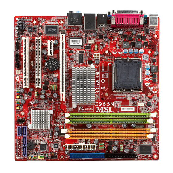
Page 13: Mainboard Layout
M: CS -Out B:SS-Ou t PCI E2 BATT VT6307/ VT6308 JMicron PCI 1 Intel Jm20335 ICH8R/DO/DH PCI 2 ALC883 /ALC888 SATA5 SATA3 SATA1 PWRFAN1 J1394_1 JCOM1 JSPD1 JUSB2 JUSB3 SATA6 SATA4 SATA2 JAUD1 CD _IN 1 (optional) G965MDH/Q965MDO Series (MS-7276 v1.X) Mainboard... -
Page 14: Packing Checklist
Getting Started Packing Checklist MSI Driver/Utility CD SATA Cable (Optional) MSI motherboard Standard Cable for Back IO Shield Power Cable IDE Devices User’s Guide * The pictures are for reference only. Your packing contents may vary depending on the model you purchased. -
Page 15: Chapter 2 Hardware Setup
Hardware Setup Chapter 2 Hardware Setup This chapter provides you with the information about hardware setup procedures. While doing the installation, be careful in holding the components and follow the installation procedures. For some components, if you install in the wrong orientation, the components will not work properly. -
Page 16: Quick Components Guide
M S-7276 M ainboard Quick Components Guide CPUFAN1, p.2-14 SYSFAN1, p.2-14 DDRII DIMMs, p.2-7 CPU, p.2-3 JPW1, p.2-9 JLPC1, p.2-18 JCI1, p.2-14 Back Panel, FDD1, p.2-12 p.2-10 IDE1, p.2-12 JPWR1, p.2-9 PCIE x16 Slot, p.2-20 JSPI1, p.2-18 PCIE x1 Slot, JBAT1, p.2-19 p.2-20 JFP2, p.2-16... -
Page 17: Cpu (Central Processing Unit)
LGA 775 package. W hen you are installing the CPU, make sure to install the cooler to prevent overheating. If you do not have the CPU cooler, contact your dealer to purchase and install them before turning on the computer. For the latest information about CPU, please visit http://www.msi.com.tw/program/ products/mainboard/mbd/pro_mbd_cpu_support.php Important 1. -
Page 18: Cpu & Cooler Installation
M S-7276 M ainboard CPU & Cooler Installation W hen you are installing the CPU, make sure the CPU has a cooler attached on the top to prevent overheating. If you do not have the cooler, contact your dealer to purchase and install them before turning on the computer. Meanwhile, do not forget to apply some silicon heat transfer compound on CPU before installing the heat sink/ cooler fan for better heat dispersion. - Page 19 Hardware Setup Important 1. Confirm if your CPU cooler is firmly installed before turning on your system. 2. Do not touch the CPU socket pins to avoid damaging. 3. The availability of the CPU land side cover depends on your CPU packing. 5.
- Page 20 M S-7276 M ainboard 9. Press down the load lever lightly 10. Align the holes on the mainboard onto the load plate, and then se- with the heatsink. Push down the cure the lever with the hook under c ooler u nti l i ts f ou r c lip s g et retention tab.
-
Page 21: Memory
Hardware Setup Memory he mainboard provides four 240-pin non-ECC DDRII 800/ 667/ 533 DIMM slots. For more information on compatible components, please visit http://www.msi.com.tw/ program/products/mainboard/mbd/pro_mbd_trp_list.php DDRII 240-pin, 1.8V 64x2=128 pin 56x2=112 pin Dual-Channel: Channel A in GREEN; Channel B in ORANGE... -
Page 22: Installing Ddrii Modules
M S-7276 M ainboard Installing DDRII Modules 1. The memory module has only one notch on the center and will only fit in the right orientation. 2. Insert the memory module vertically into the DIMM slot. Then push it in until the golden finger on the memory module is deeply inserted in the DIMM slot. -
Page 23: Power Supply
Hardware Setup Power Supply ATX 24-Pin Power Connector: ATXPWR1 This connector allows you to connect an ATX 24-pin power supply. pin 13 To connect the ATX 24-pin power supply, make sure the plug of the power supply is inserted in the proper orientation and the pins are aligned. -
Page 24: Back Panel
M S-7276 M ainboard Back Panel RS-Out L-In IEEE1394 Parallel Port M ou se Port (optional) USB Ports Keyboard Serial Port VGA Port L-Out CS-Out SS-Out M ouse/Keyboard Connector The standard PS/2 ® mouse/keyboard DIN connector is for a PS/2 ®... - Page 25 Hardware Setup USB Connectors The OHCI (Open Host Controller Interface) Universal Serial Bus root is for attaching USB devices such as keyboard, mouse, or other USB-compatible devices. Audio Port Connectors These audio connectors are used for audio devices. You can differentiate the color of the audio jacks for different audio sound effects.
-
Page 26: Connectors
M S-7276 M ainboard Connectors Floppy Disk Drive Connector: FDD1 This standard FDD connector supports 360K, 720K, 1.2M, 1.44M and 2.88M floppy disk types. FDD1 Hard Disk Connector: IDE1 (optional) The mainboard provides a USB to IDE connector that supports Ultra DMA 66 function. You can connect hard disk drives, CD-ROM drives and other IDE devices. -
Page 27: Serial Ataii Connectors: Sata1~Sata6
Hardware Setup Serial ATAII Connectors: SATA1~SATA6 SATA1~SATA6 are high-speed Serial ATA interface ports. Each supports 2 genera- tion serial ATA data rates of 300MB/s and is fully compliant with Serial ATA 2.0 specifications. Each Serial ATA connector can connect to 1 hard disk device. SATA5 SATA3 SATA1... -
Page 28: Fan Power Connectors: Cpufan1, Sysfan1 & Pwrfan1
M S-7276 M ainboard Fan Power Connectors: CPUFAN1, SYSFAN1 & PWRFAN1 The fan power connectors support system cooling fan with +12V. W hen connecting the wire to the connectors, always take note that the red wire is the positive and should be connected to the +12V, the black wire is Ground and should be connected to GND. -
Page 29: Front Panel Audio Connector: Jaud1
Hardware Setup Front Panel Audio Connector: JAUD1 The JAUD1 front panel audio connector allows you to connect the front panel audio and is compliant with Intel Front Panel I/O Connectivity Design Guide. ® JAUD1 JAUD1 Pin Definition SIGNAL DESCRIPTION AUD_MIC Front panel microphone input signal AUD_GND Ground used by analog audio circuits... -
Page 30: Front Panel Connectors: Jfp1/Jfp2
M S-7276 M ainboard Front Panel Connectors: JFP1/JFP2 The mainboard provides two front panel connectors for electrical connection to the front panel switches and LEDs. The JFP1 is compliant with Intel ® Front Panel I/O Connectivity Design Guide. JFP2 JFP1 Power Power Speaker... -
Page 31: Front Usb Connectors: Jusb1, Jusb2, Jusb3 (Jusb1 Is Optional)
Hardware Setup Front USB Connectors: JUSB1, JUSB2, JUSB3 (JUSB1 is optional) The mainboard provides USB 2.0 pinheaders (optional USB 2.0 bracket available) that are compliant with Intel ® I/O Connectivity Design Guide. USB 2.0 technology increases data transfer rate up to a maximum throughput of 480Mbps, which is 40 times faster than USB 1.1, and is ideal for connecting high-speed USB interface peripherals such as USB HDD, digital cameras, M P3 players, printers, modems and the like. -
Page 32: Ieee 1394 Connectors: J1394_1 (Optional)
M S-7276 M ainboard IEEE 1394 Connectors: J1394_1 (Optional) The mainboard provides IEEE1394 pinheaders that allow you to connect IEEE 1394 ports via an external IEEE1394 bracket (optional). Pin Definition SIGNAL SIGNAL TPA+ TPA- Ground Ground J1394_1 TPB+ TPB- Cable power Cable power Key (no pin) Ground... -
Page 33: Jumpers
Hardware Setup Jumpers Clear CMOS Jumper: JBAT1 There is a CMOS RAM onboard that has a power supply from external battery to keep the data of system configuration. With the CMOS RAM, the system can automatically boot OS every time it is turned on. If you want to clear the system configuration, set the JBAT1 (Clear CMOS Jumper ) to clear data. -
Page 34: Slots
M S-7276 M ainboard Slots PCI (Peripheral Component Interconnect) Express Slots PCI Express architecture provides a high performance I/O infrastructure for Desktop Platforms with transfer rates starting at 2.5 Giga transfers per second over a PCI Express x1 lane for Gigabit Ethernet, TV Tuners, 1394 controllers, and general pur- pose I/O. -
Page 35: Pci Interrupt Request Routing
Hardware Setup PCI Interrupt Request Routing The IRQ, acronym of interrupt request line and pronounced I-R-Q, are hardware lines over which devices can send interrupt signals to the microprocessor. The PCI IRQ pins are typically connected to the PCI bus pins as follows: Order 1 Order 2 Order 3... -
Page 36: Chapter 3 Bios Setup
BIOS Setup Chapter 3 BIOS Setup This chapter provides information on the BIOS Setup program and allows you to configure the system for optimum use. You may need to run the Setup program when: ² An error message appears on the screen during the system booting up, and requests you to run SETUP. -
Page 37: Entering Setup
M S-7276 M ainboard Entering Setup Power on the computer and the system will start POST (Power On Self Test) process. W hen the message below appears on the screen, press <DEL> key to enter Setup. Press DEL to enter SETUP If the message disappears before you respond and you still wish to enter Setup, restart the system by turning it OFF and On or pressing the RESET button. -
Page 38: The Main Menu
BIOS Setup Control Keys Move to the previous item < > Move to the next item < > Move to the item in the left hand < > Move to the item in the right hand < > Select the item <Enter>... -
Page 39: The Main Menu
M S-7276 M ainboard The Main Menu Standard CM OS Features Use this menu for basic system configurations, such as time, date etc. Advanced BIOS Features Use this menu to setup the items of AMI ® special enhanced features. Advanced Chipset Features Use this menu to change the values in the chipset registers and optimize your system’s performance. - Page 40 BIOS Setup BIOS Setting Password Use this menu to set the password for BIOS. Save & Exit Setup Save changes to CMOS and exit setup. Exit Without Saving Abandon all changes and exit setup.
-
Page 41: Standard Cmos Features
M S-7276 M ainboard Standard CMOS Features The items in Standard CMOS Features Menu includes some basic setup items. Use the arrow keys to highlight the item and then use the <PgUp> or <PgDn> keys to select the value you want in each item. Date (MM:DD:YY) This allows you to set the system to the date that you want (usually the current date). - Page 42 BIOS Setup Device/ Vender/ Size It will showing the device information that you connected to the IDE/SATA con- nector . LBA/Large M ode This allows you to enable or disable the LBA Mode. Setting to Auto enables LBA mode if the device supports it and the devices is not already formatted with LBA mode disabled.
- Page 43 M S-7276 M ainboard System Information Press <Enter> to enter the sub-menu, and the following screen appears. This sub-menu shows the CPU information, BIOS version and memory status of your system (read only).
-
Page 44: Advanced Bios Features
BIOS Setup Advanced BIOS Features Quick Boot Setting the item to [Enabled] allows the system to boot within 10 seconds since it will skip some check items. Boot to OS/2 This allows you to run the OS/2 ® operating system with DRAM larger than 64MB. W hen you choose [No], you cannot run the OS/2 ®... - Page 45 M S-7276 M ainboard Important Enabling the functionality of Hyper-Threading Technology for your computer system requires ALL of the following platform Components: CPU: An Intel ® Pentium ® 4 Processor with HT Technology; Chipset: An Intel ® Chipset that supports HT Technology; BIOS: A BIOS that supports HT Technology and has it enabled;...
-
Page 46: Advanced Chipset Features
BIOS Setup Advanced Chipset Features Configure DRAM Timing by SPD The system board designer must select the proper value for this field, according to the specifications of the installed DRAM chips. W hen Disabled, you can select the DRAM timing type. M emory Hole In order to improve performance, certain space in memory can be reserved for ISA peripherals. - Page 47 M S-7276 M ainboard ME-HECI This field allows you to enable/disable ME-HECI. ME-IDER This field allows you to enable/disable ME-IDER. ME-KT This field allows you to enable/disable ME-KT. 3-12...
-
Page 48: Integrated Peripherals
BIOS Setup Integrated Peripherals USB 2.0 Controller This setting allows you to enable/disable the onboard USB controller. USB Device Legacy Support Select [Enabled] if you need to use a USB-interfaced device in the operating system. USB 2.0 Controller Mode This setting allows you to select the USB controller mode. BIOS EHCI Hand-Off This item can used to stop the EHCI legacy for operations systems without EHCI hand-off mechanism loading properly. - Page 49 M S-7276 M ainboard Audio Controller This setting is used to enable/disable the onboard audio controller. SATA Device Configuration Press <Enter> to enter the sub-menu and the following screen appears: SATA#1 Configuration It allows you to configure the SATA#1 controller.Settings are: [Disabled] Disable the SATA devices [Compatible]...
- Page 50 BIOS Setup Onboard Floppy Controller Select [Enabled] if your system has a floppy disk controller (FDD) installed on the system board and you wish to use it. If you install add-on FDC or the system has no floppy drive, select [Disabled] in this field. COM Port 1/ 2 Select an address and corresponding interrupt for the serial port 1/ 2.
-
Page 51: Power Management Setup
M S-7276 M ainboard Power Management Setup Important S3-related functions described in this section are available only when your BIOS supports S3 sleep mode. Energy Lake Feature (optional, only for ICH8DH) This item allows you to enable Intel’s “Energy Lake” Technology which can support Viiv feature to turn on and turn off the computer instantly. - Page 52 BIOS Setup information stored in memory will be used to restore the sys- tem when a “wake up” event occurs. Re-Call VGA BIOS From S3 W hen ACPI Standby State is set to [S3/STR], users can select the options in this field.
- Page 53 M S-7276 M ainboard S3 Power on by PS/2 KB The item specifies how the system will be awakened from power saving mode when input signal of the PS2 keyboard is detected. Use the <PageUp> & <PageDown> keys to select the options. W hen selecting [Password], enter the desired password.
-
Page 54: Pnp/Pci Configurations
BIOS Setup PNP/PCI Configurations This section describes configuring the PCI bus system and PnP (Plug & Play) feature. PCI, or Peripheral Component Interconnect, is a system which allows I/O devices to operate at speeds nearing the speed the CPU itself uses when communicating with its special components. - Page 55 M S-7276 M ainboard IRQ Resource Setup Press <Enter> to enter the sub-menu and the following screen appears. IRQ 3/4/5/7/9/10/11/14/15 These items specify the bus where the specified IRQ line is used. The settings determine if AMIBIOS should remove an IRQ from the pool of avail- able IRQs passed to devices that are configurable by the system BIOS.
-
Page 56: H/W Monitor
BIOS Setup H/W Monitor FAN Speed Monitor 1 / 2 / 3 (optional) This item allows you to enable/disable the FAN Speed Monitors. AFSC Configuration (optional) This item allows you to lock/unlock AFSC (Advanced Fan Speed Control) Configuration. AFSC SST BUS (optional) This item allows you to lock/unlock AFSC SST (Simple Serial Transport) Bus. - Page 57 M S-7276 M ainboard Chassis Intrusion The field enables or disables the feature of recording the chassis intrusion status and issuing a warning message if the chassis is once opened. To clear the warning message, set the field to [Reset]. The setting of the field will automatically return to [Enabled] later.
-
Page 58: Load Optimized Defaults
BIOS Setup Load Optimized Defaults The option on the main menu allows users to restore all of the BIOS settings to the default Optimized values. The Optimized Defaults are the default values set by the mainboard manufacturer specifically for optimal performance of the mainboard. W hen you select Load Optimized Defaults, a message as below appears: Pressing Y loads the default factory settings for optimal system performance. -
Page 59: Bios Setting Password
M S-7276 M ainboard BIOS Setting Password W hen you select this function, a message as below will appear on the screen: Type the password, up to six characters in length, and press <Enter>. The password typed now will replace any previously set password from CMOS memory. You will be prompted to confirm the password. -
Page 60: Appendix A Realtek Alc883 Audio
Realtek ALC883 Audio Appendix A Realtek ALC883 Audio The Realtek ALC883 provides 10-channel DAC that si- multaneously supports 7.1 sound playback and 2 chan- nels of independent s tereo s ound output (multiple streaming) through the Front-Out-Left and Front-Out- Right channels. -
Page 61: Installation For Windows 2000/Xp
M S-7276 M ainboard Installing the Realtek HD Audio Driver You need to install the driver for Realtek ALC883 codec to function properly before you can get access to 2-, 4-, 6-, 8- channel or 7.1+2 channel audio operations. Follow the procedures described below to install the drivers for different operating systems. - Page 62 Realtek ALC883 Audio 3. Click Next to install the Realtek High Definition Audio Driver. Click here 4. Click Finish to restart the system. S el ec t t hi s option Click here...
-
Page 63: Software Configuration
M S-7276 M ainboard Software Configuration After installing the audio driver, you are able to use the 2-, 4-, 6- or 8- channel audio feature now. Click the audio icon from the system tray at the lower-right corner of the screen to activate the HD Audio Configuration. It is also available to enable the audio driver by clicking the Azalia HD Sound Effect M anager from the Control Panel. -
Page 64: Sound Effect
Realtek ALC883 Audio Sound Effect Here you can select a sound effect you like from the Environment list. Environment Simulation You will be able to enjoy different sound experience by pulling down the arrow, totally 23 kinds of sound effect will be shown for selection. Realtek HD Audio Sound Manager also provides five popular settings “Stone Corridor”, “Bathroom”, “Sewer pipe”, “Arena”... - Page 65 M S-7276 M ainboard Equalizer Selection Equalizer frees users from default settings; users may create their owned preferred settings by utilizing this tool. 10 bands of equalizer, ranging from 100Hz to 16KHz. Save Reset The settings are saved 10 bands of equalizer permanently for future would go back to the de- fault setting...
- Page 66 Realtek ALC883 Audio Frequently Used Equalizer Setting Realtek recognizes the needs that you might have. By leveraging our long experience at audio field, Realtek HD Audio Sound Manager provides you certain optimized equal- izer settings that are frequently used for your quick enjoyment. [How to Use It] Other than the buttons “Pop”...
-
Page 67: Mixer
M S-7276 M ainboard Mixer In the Mixer part, you may adjust the volumes of the rear and front panels individually. 1. Adjust Volume You can adjust the volume of the speakers that you pluged in front or rear panel. Important Before set up, please make sure the playback devices are well plugged in the jacks on the rear or front panel. - Page 68 Realtek ALC883 Audio W hen you are playing the first audio source (for example: use W indows Media Player to play DVD/VCD), the output will be played from the rear panel, which is the default setting. Then you must to select the Realtek HD Audio 2nd output from the scroll list first, and use a different program to play the second audio source (for example: use Winamp to play MP3 files).
-
Page 69: Playback Control
M S-7276 M ainboard 3. Playback control Playback device Tool Mute This function is to let you freely decide which ports to output the sound. And this is essential when multi- streaming playback enabled. - Realtek HD Audio Output - Realtek HD Audio 2nd Output M u te You may choose to mute single or multiple volume controls or to completely mute sound output. - Page 70 Realtek ALC883 Audio 4. Recording control Recording device Tool Mute -Realtek HD Digital input -Realtek HD Audio input M u te You may choose to mute single or multiple volume controls or to completely mute sound input. Tool - Show the following volume controls This is to let you freely decide which volume control items to be displayed.
-
Page 71: Audio I/O
M S-7276 M ainboard Audio I/O In this tab, you can easily configure your multi-channel audio function and speakers. You can choose a desired multi-channel operation here. a. Headphone for the common headphone b. 2CH Speaker for Stereo-Speaker Output c. 4CH Speaker for 4-Speaker Output d. - Page 72 Realtek ALC883 Audio Connector Settings Click to access connector settings. Disable front panel jack detection (option) Jack detection function only works with HD audio front panel. M ute rear panel output when front headphone plugged in. Enable auto popup dialogue, when device has been plugged in Once this item checked, the dialog “Connected device”...
- Page 73 M S-7276 M ainboard S/PDIF Short for Sony/Philips Digital Interface, a standard audio file transfer format. S/PDIF allows the transfer of digital audio signals from one device to another without having to be converted first to an analog format. Maintaining the viability of a digital signal prevents the quality of the signal from degrading when it is converted to analog.
- Page 74 Realtek ALC883 Audio Test Speakers You can select the speaker by clicking it to test its functionality. The one you select will light up and make testing sound. If any speaker fails to make sound, then check whether the cable is inserted firmly to the connector or replace the bad speakers with good ones.
-
Page 75: Microphone
M S-7276 M ainboard Microphone In this tab you may set the function of the microphone. Select the Noise Suppres- sion to remove the possible noise during recording, or select Acoustic Echo Cancelltion to cancel the acoustic echo druing recording. Acoustic Echo Cancelltion prevents playback sound from being recorded by mi- crophone together with your sound. -
Page 76: 3D Audio Demo
Realtek ALC883 Audio 3D Audio Demo In this tab you may adjust your 3D positional audio before playing 3D audio applica- tions like gaming. You may also select different environment to choose the most suitable environment you like. A-17... -
Page 77: Information
M S-7276 M ainboard Information In this tab it provides some information about this HD Audio Configuration utility, including Audio Driver Version, DirectX Version, Audio Controller & Audio Codec. You may also select the language of this utility by choosing from the Language list. Also there is a selection Show icon in system tray. -
Page 78: Hardware Setup
Realtek ALC883 Audio Hardware Setup Connecting the Speakers W hen you have set the Multi-Channel Audio Function mode properly in the software utility, connect your speakers to the correct phone jacks in accordance with the setting in software utility. n 2-Channel M ode for Stereo-Speaker Output Refer to the following diagram and caption for the function of each phone jack on the back panel when 2-Channel Mode is selected. - Page 79 M S-7276 M ainboard n 4-Channel M ode for 4-Speaker Output Back Panel Description: Connect two speakers to back panel’s front-channel Line Out connector and two speakers to t he r eal- c h an n el L in e O u t connector.
- Page 80 Realtek ALC883 Audio n 6-Channel M ode for 6-Speaker Output Back Panel Description: Connect two speakers to back panel’s Line Out connector, two speakers to the rear-channel Line out connec tor and two s p e a k e r s t o t h e c e n t e r / subwoofer-channel Line Out 6-Channel Analog Audio Output connector.
- Page 81 M S-7276 M ainboard n 8-Channel M ode for 8-Speaker Output Description: Connect two speakers to back panel’s Line Out connector, two speakers to the rear-channel Line out connector, two speak- ers to the center/subwoofer- channel Line Out connector and 8-Channel Analog Audio Output two speakers to the side-chan- nel Line Out connector.
-
Page 82: Appendix B Intel Ich8R/Do/Dh Sata Raid
Intel ICH8R/DO/DH SATA RAID Appendix B Intel ICH8R/DO/DH SATA RAID The ICH8R/DO/DH provides a hybrid solution that com- bines six independent SATAII ports for support of up to six Serial ATAII (Serial ATAII RAID) drives. It offers RAID level 0 (Striping), RAID level 1 (Mirroring and Duplexing), RAID level 5 (Block Interleaved Distrib- uted Parity), RAID level 10 (A Stripe of Mirrors) and Intel... -
Page 83: Ich8R/Do/Dh Introduction
M S-7276 M ainboard ICH8R/DO/DH Introduction The ICH8R/DO/DH provides a hybrid solution that combines 6 independent SATAII ports for support of up to 6 Serial ATAII (Serial ATAII RAID) drives. Serial ATAII (SATAII) is the latest generation of the ATA interface. SATA hard drives deliver blistering transfer speeds up to 300MB/sec. -
Page 84: Bios Configuration
Intel ICH8R/DO/DH SATA RAID BIOS Configuration The Intel Matrix Storage Manager Option ROM should be integrated with the system BIOS on all motherboards with a supported Intel chipset. The Intel Matrix Stroage Manager Option ROM is the Intel RAID implementation and provides BIOS and DOS disk services. - Page 85 M S-7276 M ainboard After pressing the <Ctrl> and <I> keys simultaneously, the following window will appear: (1) Create RAID Volume Select option 1 “Create RAID Volume” and press <Enter> key. The following screen appears. Then in the Name field, specify a RAID Volume name and then press the <TAB>...
- Page 86 Intel ICH8R/DO/DH SATA RAID In the Disk field, press <Enter> key and the following screen appears. Use <Space> key to select the disks you want to create for the RAID volume, then click <Enter> key to finish selection. Then select the strip value for the RAID array by using the “upper arrow” or “down arrow”...
- Page 87 M S-7276 M ainboard Important Since you want to create two volumes (Intel Matrix RAID Technology), this default size (maximum) needs to be reduced. Type in a new size for the first volume. As an example: if you want the first volume to span the first half of the two disks, re-type the size to be half of what is shown by default.
- Page 88 Intel ICH8R/DO/DH SATA RAID (2) Delete RAID Volume Here you can delete the RAID volume, but please be noted that all data on RAID drives will be lost. Important If your system currently boots to RAID and you delete the RAID volume in the Intel RAID Option ROM, your system will become unbootable.
- Page 89 M S-7276 M ainboard (3) Reset Disks to Non-RAID Select option 3 Reset Disks to Non-RAID and press <Enter> to delete the RAID volume and remove any RAID structures from the drives. The following screen appears: Press <Y> key to accept the selection. Important 1.
-
Page 90: Installing Software
Please follow the instruction below to make an “Intel IAA RAID Driver For ICH8R” for yourself. 1. Insert the MSI CD into the CD-ROM drive. 2. Click the “Browse CD” on the Setup screen. 3. Copy all the contents in \\IDE\Intel\ICH8R\Floppy to a formatted floppy diskette. -
Page 91: Installation Of Intel Matrix Storage Console
For this reason, you cannot remove or un-install this driver from the system after installation; however, you will have the ability to un-install all other non-driver components. Insert the MSI CD and click on the Intel IAA RAID Edition to install the software. Click on this item B-10... - Page 92 Intel ICH8R/DO/DH SATA RAID The InstallShield Wizard will begin automatically for installation showed as following: Click on the Next button to proceed the installation in the welcoming window. B-11...
- Page 93 M S-7276 M ainboard The window shows the components to be installed. Click Next button to continue. After reading the license agreement in the following window, click Yes button to continue. B-12...
- Page 94 Intel ICH8R/DO/DH SATA RAID The following window appears to show the Readme File Information. It shows the system requirements and installation information. Once the installation is complete, the following window appears. B-13...
-
Page 95: Raid Migration Instructions
M S-7276 M ainboard RAID Migration Instructions The Intel Matrix Storage Console offers the flexibility to upgrade from a single Serial ATA (SATA) hard drive to RAID configuration when an additional SATA hard drive is added to the system. This process will create a new RAID volume from an existing disk. -
Page 96: Create Raid Volume From Existing Disk
Intel ICH8R/DO/DH SATA RAID Create RAID Volume from Existing Disk To create a RAID volume from an existing disk, choose Action --> Create RAID Volume from Existing Hard Drive. The Create RAID Volume from Existing Hard Drive Wizard pops up to lead you for the following procedure. - Page 97 M S-7276 M ainboard (1) Step 1: Configure Volume Here you can configure the new RAID volume by entering the volume name, selecting the RAID level and strip size. † RAID Volume Name: A desired RAID volume name needs to be typed in where the ‘RAID_Volume1’ text currently appears above.
- Page 98 Intel ICH8R/DO/DH SATA RAID expensive (requiring read-in prior to write, in order to be able to calculate the correct parity information), or similar to RAID-1 writes. The write efficiency depends heavily on the amount of memory in the machine, and the usage pattern of the array.
- Page 99 M S-7276 M ainboard (3) Select Member Hard Drive(s) Then select the member disk (the target disk) that you wish to use and then click “- -->” to move it to the Selected field. Then click Next to continue. Please note that the existing data on the selected hard drive(s) will be deleted permanently.
- Page 100 Intel ICH8R/DO/DH SATA RAID (4) Specify Volume Size Specify the amount of available array space to be used by the new RAID volume. You may enter the amount in the space or use the slider to specify. It is recommended you use 100% of the available space for the optimized usage.
- Page 101 M S-7276 M ainboard (6) Start Migration The migration process may take up to two hours to complete depending on the size of the disks being used and the strip size selected. A dialogue window will appear stating that the migration process may take considerable time to complete, meanwhile a popup dialogue at the taskbar will also show the migration status.
-
Page 102: Degraded Raid Array
Intel ICH8R/DO/DH SATA RAID Degraded RAID Array A RAID 1, RAID 5 or RAID 10 volume is reported as degraded when one of its hard drive members fails or is temporarily disconnected, and data mirroring is lost. As a result, the system can only utilize theremaining functional hard drive member. To re- establish data mirroring and restore data redundancy, refer to the procedure below that corresponds to the current situation. - Page 103 M S-7276 M ainboard 5. Exit Intel RAID Option ROM, and then reboot to W indows system. 6. W hen prompted to rebuild the RAID volume, click 'Yes'. 7. The Intel(R) Storage Utility will be launched. Right-click the new hard drive and select 'Rebuild to this Disk'.
Need help?
Do you have a question about the G965MDH Series and is the answer not in the manual?
Questions and answers