Table of Contents
Advertisement
Available languages
Available languages
Quick Links
Advertisement
Table of Contents

Subscribe to Our Youtube Channel
Related Manuals for MSI MS-7203


Summary of Contents for MSI MS-7203
- Page 1 P4N SLI XE Series MS-7203 (V1.X) Mainboard G52-M7203X1...
-
Page 2: Copyright Notice
If a problem arises with your system and no solution can be obtained from the user’s manual, please contact your place of purchase or local distributor. Alternatively, please try the following help resources for further guidance. Visit the MSI website for FAQ, technical guide, BIOS updates, driver updates, and other information: http://www.msi.com.tw/program/service/faq/ faq/esc_faq_list.php... -
Page 3: Safety Instructions
Safety Instructions Always read the safety instructions carefully. Keep this User’s Manual for future reference. Keep this equipment away from humidity. Lay this equipment on a reliable flat surface before setting it up. The openings on the enclosure are for air convection hence protects the equip- ment from overheating. -
Page 4: Fcc-B Radio Frequency Interference Statement
VOIR LA NOTICE D’INSTALLATION AVANT DE RACCORDER AU RESEAU. Micro-Star International MS-7203 This device complies with Part 15 of the FCC Rules. Operation is subject to the following two conditions: (1) this device may not cause harmful interference, and (2) this device must accept any interference received, including interference that may cause undesired operation. -
Page 5: Weee (Waste Electrical And Electronic Equipment) Statement
WEEE (Waste Electrical and Electronic Equipment) Statement... -
Page 8: Table Of Contents
CONTENTS Copyright Notice ......................ii Tradema rks ........................ii Revision History ......................ii Technical Support ...................... ii Safety Instructions ....................iii FCC-B Radio Frequency Interference Statement ..........iv WEEE (Waste Electrical and Electronic Equipment) Statement ....... v English ........................En-1 G e rm an ........................ -
Page 9: Installation Guide
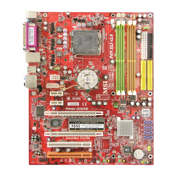
Non SLI mode - PCI_E1 slot is compatible with PCI Express x16 speed, and the PCI_E2 slot is compatible with PCI Express x 1 speed. - 2 PCI Express x 1 slots - 2 PCI slots includes one orange slot which supports 2 master for MSI special PCI function card (ex. wireless LAN and bluetooth combo card.). Form Factor - ATX (30.5 cm X 24.4 cm) - Page 10 M S-7203 M ainboard Layout of P4N SLI XE Series (MS-7203 v1.X) Mainboard En-2...
-
Page 11: How To Use This Installation Guide
Installation Guide “How to use this Installation Guide?” This installation guide is designed for you to easily install the mainboard. Follow the steps below to use this guide: - Read the specifications of the mainboard first on page En-1. - Find out the component with the component number at your desire from the layout of the mainboard on page En-2. - Find out the component description and installing instructions with the “Components Index Table”... - Page 12 ® The mainboard supports Intel processor. The mainboard uses a CPU socket called Socket-775 for easy CPU installation. For the latest information about CPU, please visit http://www.msi.com.tw/program/products/mainboard/mbd/ pro_mbd_cpu_support.php. Important Overheating Overheating will seriously damage the CPU and system, always make sure the cooling fan can work properly to protect the CPU from overheating.
- Page 13 Installation Guide Memory Specification : 184-pin, 2.5v. Single channel definition : All DIMM slots are GREEN color. Dual channels definition : DIMM slot(s) on Channel A are marked in GREEN color. DIMM slot(s) on Channel B are marked in Purple color. 40x2=80 pin 52x2=104 pin DDRII...
- Page 14 M S-7203 M ainboard Connectors, Jumper, Slots Fan Power Connectors The fan power connectors support system cooling fan with +12V. The CPUFAN1 supports Smart FAN function. When connect the wire to the connectors, always take note that the red wire is the positive and should be connected to the +12V, the black wire is Ground and should be connected to GND.
- Page 15 Installation Guide Front Panel Connectors These two front panel connectors are used for electrical connection to the front panel switches and LEDs. JFP1 is compliant ® with Intel Front Panel I/O Connectivity Design Guide. Power Power Switch Power LED JFP2 JFP1 Reset Speaker...
- Page 16 M S-7203 M ainboard Front Panel Audio Connector Ground port1 _L The front panel audio connector allows you to connect to the front panel audio and ® is compliant with Intel Front Panel I/O Connectivity Design Guide. port1 _R Presence# port2_R Sense1_Return Sense_Send...
- Page 17 Installation Guide D-Bracket™ 2 Connector The connector is for you to connect D-Bracket™ 2. D-Bracket™ 2 is a external USB Bracket that support both USB1.1 & 2.0 spec. It integrates four LEDs and allows users to identify system problem through 16 various combinations of LED signals.
- Page 18 M S-7203 M ainboard Clear CMOS Button The CMOS RAM onboard has a power supply from external battery to keep the data of system configuration. With the CMOS RAM, the system can automatically boot OS every time it is turned on. If you want to clear the system configuration, use the Clear CMOS Button to clear data.
- Page 19 Installation Guide PCI Express Slots (x16/ x4/ x1) The PCI Express slot, as a high-bandwidth, low pin count, serial, interconnect technology. PCI Express architecture provides a high performance I/O infrastructure for Desktop Platforms with transfer rates starting at 2.5 Giga transfers per second over a PCI Express x1 lane for Gigabit Ethernet, TV Tuners, 1394 controllers, and general purpose I/O.
-
Page 20: Back Panel
M S-7203 M ainboard Back Panel Mouse/Keyboard Connector ® ® ® The standard PS/2 mouse/keyboard mini DIN connector for attaching a PS/2 mouse/keyboard. You can plug a PS/2 mouse/keyboard directly into this connector. The connector location and pin assignments are as follows: PS/2 Mouse connector (Green/ 6-pin female) PS/2 Keyboard connector (Purple/ 6-pin female) Parallel Port Connector... - Page 21 Installation Guide LAN (RJ-45) Jack The standard RJ-45 jack for connection to single Local Area Network (LAN). You can connect a network cable to it. Activity Indicator Link Indicator Color LED State Condition LAN link is not established. Left Orange On (steady state) LAN link is established.
-
Page 22: Bios Setup
M S-7203 M ainboard BIOS Setup This chapter provides basic information on the BIOS Setup program and allows you to configure the system for optimum use. You may need to run the Setup program when: * An error message appears on the screen during the system booting up, and requests you to run BIOS SETUP. * You want to change the default settings for customized features. - Page 23 Installation Guide The Main Menu ® ® Once you enter AMI or AWARD BIOS CMOS Setup Utility, the Main Menu will appear on the screen. The Main Menu allows you to select from ten setup functions and two exit choices. Use arrow keys to select among the items and press <Enter>...
-
Page 24: English
Utility menu - The Utility menu shows the software applications that the mainboard supports. WebSite menu- The WebSite menu shows the necessary websites. Important Please visit the MSI website to get the latest drivers and BIOS for better system performance. En-16... - Page 25 *Bitte besuchen Sie http://www.ms i.com.tw/ program/produc ts/mainboard/ mbd/ pro_mbd_c pu_support.php um die neues ten Informationen zu unterstützten Prozessoren zu erhalten **Den letzten St and bezügli ch der unt erstützten Speichermodule finden Sie unter http://www. msi.com.tw/ program/pro ducts/ ma inbo ard/ mbd/pro _mbd_trp_ li st .php...
- Page 26 M S-7203 M ainboard Layout des Mainboards P4N SLI XE Serie (MS-7203 v1.X) De-2...
- Page 27 Installationsanleitung “Wie Sie diese Installationsanleitung verwenden.” Diese Installationsanleitung wurde so gestaltet, dass Sie Ihnen die einfache Installation Ihres Mainboards ermöglicht. Folgen Sie den Schritten unten zur Nutzung dieser Anleitung: - Lesen Sie zunächst die Spezifikationen dieses Mainboards auf der Seite De-1 durch. - Identifizieren Sie die fragliche Komponente anhand der Nummerierung im Mainboardlayout auf der Seite De-2.
- Page 28 M S-7203 M ainboard Hauptprozessor: CPU ® Das Mainboard unterstützt Intel Prozessoren und verwendet hierfür einen CPU Sockel mit der Bezeichnung Sockel- 775, um das Einsetzen der CPU zu erleichtern. wichtig Überhitzung Überhitzung beschädigt die CPU und das System nachhaltig, stellen Sie stets eine korrekte Funktionsweise des CPU Kühlers sicher, um die CPU vor Überhitzung zu schützen.
- Page 29 Installationsanleitung Speicher Spezifikation : 184-Pin, 2,5V. Bestimmung Einkanalbetrieb : Alle DIMM Slots sind GRÜN. Bestimmung Zweikanalbetrieb : Die DIMM Slot(s) des Kanals A sind in GRÜN gehalten. Die DIMM Slot(s) des Kanals B sind LILA. 40x2=80 Pin 52x2=104 Pin DDR 2 Spezifikation : 240-Pin, 1,8V.
- Page 30 M S-7203 M ainboard Anschlüsse, Steckbrücken und Slots Stromanschlüsse für Lüfter Die Anschlüsseunterstützen aktive Systemlüfter mit + 12V. Der Anschluss CPU FAN (Prozessorlüfter) unterstützt die Smart FAN Funktionalität. Wenn Sie den Anschluss herstellen, sollten Sie immer darauf achten, dass der rote Draht der positive Pol ist, und mit +12V verbunden werden sollte, der schwarze Draht ist der Erdkontakt und sollte mit GND verbunden werden.
- Page 31 Installationsanleitung Frontpaneel Anschlüsse Diese zwei Anschlüsse für das Frontpaneel dienen zum Anschluss der Schalter und LEDs des Frontpaneels. JFP1 erfüllt die Anforderungen des “Intel Front Panel I/O Connectivity Design Guide“. System System- schalter System LED JFP2 JFP1 Fest- Reset- Laut- platten schalter sprecher...
- Page 32 M S-7203 M ainboard Audioanschluss des Frontpaneels port1 _L Ground Der Audio Vorderanschluss ermöglicht den Anschluss von Audioein- und - ausgängen eines Frontpaneels. Der Anschluss entspricht den Richtlinien des “ port1 _R Presence# ® Intel Front Panel I/O Connectivity Design Guide”. port2_R Sense1_Return Sense_Send...
- Page 33 Installationsanleitung D-Bracket™ 2 Anschluss Das Mainboard verfügt über einen Anschluss für das D-Bracket™ 2. Das D-Bracket™ 2 ist ein USB Slotblech, das die Spezifikationen von USB1.1 und 2.0 erfüllt. Es beinhaltet vier LEDs und ermöglicht es dem Anwender Probleme zu identifizieren, in dem es 16 unterschiedliche Kombinationen von LED Signalen ausgibt.
- Page 34 M S-7203 M ainboard Taster zur Löschung des CMOS Auf dem Mainboard gibt es einen sogenannten CMOS Speicher (RAM), der über eine Batterie gespeist wird und die Daten der Systemkonfiguration enthält. Er ermöglicht es dem Betriebssystem, mit jedem Einschalten automatisch hochzufahren.
- Page 35 Installationsanleitung PCI Express Sockel (x16/ x4/ x1) Die PCI Express Slots verwenden eine serielle Anschlusstechnologie, die sich durch eine hohe Bandbreite und eine niedrige Anzahl an Pins auszeichnet. Die PCI Express Architektur stellt eine Hochleistungs- Ein-/Ausgabe - Infrastruktur für Desktop Plattformen mit Datendurchsätzen zur Verfügung, die bei 2,5 Giga- Übertragungen pro Sekunde über eine PCI Express x1 Leitung für Gigabit- Lan, TV -Karten, 1394 Kontroller und allgemeine Ein- und Ausgabe anfängt.
-
Page 36: Hinteres Anschlusspaneel
M S-7203 M ainboard Hinteres Anschlusspaneel Maus-/Tastaturanschluss Das Mainboard verfügt über einen Standard PS/2 ® ® Maus/Tastatur Mini DIN Anschluss um eine PS/2 Maus/Tastatur ® anzuschliessen. Sie können hier direkt eine PS/2 Maus/Tastatur anschliessen. Die Lage und Pinbelegung sind wie folgt: PS/2 Mausanschluss (Grün/ 6-Pin Buchse) PS/2 Tastaturanschluss (Lila/ 6-Pin Buchse) Parallele Schnittstelle... - Page 37 Installationsanleitung LAN (RJ-45) Buchse Das Mainboard bietet eine Standard RJ-45 Buchse zum Anschluss an ein Lokales Netzwerk (Local Area Network - LAN). Hier kann ein Netzwerkkabel angeschlossen werden. . Aktivitätsanzeige Verbindungsanzeige Farbe LED Status Zustand Keine Verbindung mit dem LAN Links Orange An (Dauerleuchten)
- Page 38 M S-7203 M ainboard BIOS Setup Dieses Kapitel enthält Informationen über das BIOS Setup und ermöglicht es Ihnen, Ihr System optimal auf Ihre Anforderungen einzustellen. Notwendigkeit zum Aufruf des BIOS besteht, wenn: * Während des Bootvorgangs des Systems eine Fehlermeldung erscheint und Sie zum Aufruf des BIOS SETUP aufgefordert werden.
- Page 39 Installationsanleitung Das Hauptmenü ® ® Nachdem Sie das AMI oder AWARD BIOS CMOS Setup Utility, aufgerufen haben, erscheint das Hauptmenü. Es weist zehn Setup- Funktionen und zwei Arten das Menü zu verlassen auf. Verwenden Sie die Pfeiltasten, um im Menü zu navigieren und drücken Sie die Eingabetaste (<Enter>), um ein Untermenü...
- Page 40 Das Softwaremenü (Utility menu) - Das Softwaremenü füht die Anwendungsprogramme auf, die das Mainboard unterstützt. WebSite Menü- Das Website Menü zeigt die notwendigen Webseiten an. wichtig Um bessere Systemleistung zu erzielen, besuchen Sie bitte die MSI Webseite, um die letzen Treiber und das aktuellste BIOS herunterzuladen. De-16...
- Page 41 - 9 Trous de montage *Pour plus d’i nf ormat ion c onc ernant le CPU, ve ui lle z vis it er ht tp: // www.msi .co m. tw/ program/product s/ ma inboa rd/ mbd/ pro_ mbd_ cpu_ support. php **Pour plus de mises à...
- Page 42 La Carte M S-7203 Carte Mère P4N SLI XE Séries (MS-7203 v1.X) Fr-2...
- Page 43 Installation Matériel “Comment utiliser ce manuel?” Ce manuel de l’utilisateur fournit des instructions pour installer la carte Mère . Veuillez suivre les instructions - Voyez la Spécificités de la Carte Mère à la page Fr-1. - Découvrez le tableau avec le nombre composant de la disposition de la carte mère à la page Fr-2. - Découvrez la description composante et instruction d’installation avec le T ableau d’index Composant - En plaçant le BIOS et installez le conducteur/ utiltity si vous voulez.
- Page 44 ® La carte mère supporte les processeurs Intel . La carte utilise un socket appelé Socket-775 pour l’ installation de chaque CPU. Pour une mise à jour sur les informations relatives au CPU, veuillez visiter http://www.msi.com.tw/program/products/ mainboard/mbd/pro_mbd_cpu_support.php. importante Surchauffe Une surchauffe peut sérieusement endommager le CPU et le système, assurez vous toujours que le système de reffroidissement fonctionne correctement pour protéger le CPU d’une s urchauffe.
- Page 45 Installation Matériel Mémoire Spécification : 184-pin, 2.5v. Définition de canal unique : Tous les slots DIMM sont Verts. Définition de canaux double : Slot(s) DIMM sur le canal A est en Vert. Slot(s) DIMM sur le canal B est en violet . 40x2=80 pin 52x2=104 pin DDR 2...
- Page 46 La Carte M S-7203 Connecteurs, Jumper, Slots Connecteurs Fan Power Les connecteurs au ventilateur du système supportent la puissance du ventilateur avec +12V. Le VENTILATEUR de CPU supporte la fonction futée de VENTILATEUR(Smart FAN). Quand vous reliez le fil aux connecteurs, notez que le fil rouge est positif et doit être relié...
- Page 47 Installation Matériel Connecteur Panneau Avant La carte mère possède deux connecteurs pour la connexion électrique du panneau avant (led, switch). JFP1 est compatible ® avec l’Intel Front Panel I/O Connectivity Design Guide. Power Power Switch Power LED JFP1 JFP2 Rese et parleur Switch Connecteur Front USB 2.0 (jaune)
- Page 48 La Carte M S-7203 Connecteur facade audio port1 _L Ground Le connecteur facade audio vous permet de connecter la facade audio qui est ® compatible avec l’Intel Front Panel I/O Connectivity Design Guide. port1 _R Presence# port2_R Sense1_Return Sense_Send Clef port2_L Sense2_Return 9 10...
- Page 49 Installation Matériel Connecteur D-Bracket™ 2 Le connecteur est utilisé pour connecter le D-Bracket™ 2. Le D-Bracket™ 2 est un bracket USB externe qui supporte les spécifications USB1.1 & 2.0. Le D-Bracket est pourvu de 4 LED et permet d’identifier les problèmes et ce à l’aide de 16 combinaisons de couleurs pour de plus amples renseignements sur ces 16 signaux.
- Page 50 La Carte M S-7203 Clear CMOS Bouton La mémoire du Bios est alimentée à partir de la pile afin de conserver les données de la configuration du système. Avec la mémoire du Bios, le système peut automatiquement démarrer sur l’OS à chaque fois lorsqu’il est allumé. Si vous voulez effacer la configuration du Bios, utilisez le bouton Clear CMOS.
- Page 51 Installation Matériel Slots PCI Express (x16/ x4/ x1) Le slot PCI Express, comme une largeur de bande et un pin basse, compte une publication sérielle, une technologie d’interconnexion. L’architecture PCI Express fournit un rendement élevé I/O infrastructure pour les plateformes de bureau avec un taux de transfert de 2.5 de Giga par seconde sur une voie PCI Express x1pour Gigabit Ethernet, TV Tuners, contrôleurs 1394, et IO général.
- Page 52 La Carte M S-7203 Panneau Arrière Connecteur Souris/Clavier ® ® Le connecteur PS/2 souris/clavier mini DIN est conçu pour attacher un PS/2 souris/clavier. Vous pouvez brancher ® directement un PS/2 souris/clavier dans ce connecteur. Les connecteurs et les pins sont ainsi: Connecteur PS/2 souris (Vert/ 6-pin feminin) Connecteur PS/2 clavier (Purple/ 6-pin feminin) Connecteur port Parallèle...
- Page 53 Installation Matériel LAN (RJ-45) Jack Le standard RJ-45 jack est utile pour le raccordement au Réseau de Région Local (LAN). Vous pouvez relier un câble de réseau à celui-ci. Indicateur de Lien Indicateur d’Activité Couleur LED Statu Condition Éteint Le lien de LAN n’est pas établi. Le lien de LAN est établi.
-
Page 54: Installation Du Bios
La Carte M S-7203 Installation du BIOS Ce chapitre vous informe sur le programme d’installation du BIOS et vous permet de configurer le système pour un usage optimum. Vous pouvez installer le programme lorsque: * Un message d’erreur apparaît sur l’écran pendant que le système initialise et vous demande de mettre en marche l’INSTALLATION de BIOS. - Page 55 Installation Matériel Menu Principal ® ® BIOS CMOS Setup Utility, le menu apparaît à l’écran. Le Menu permet de Une fois entré dans le AMI ou AWARD sélectionner dix fonctions et deux choix de sortie de l’utilitaire. Utilisez les flèches pour vous diriger et utilisez la touche ENTREE pour sélectionner un élément ou entrer dans le sous-menu..
-
Page 56: Information De Logiciel
Menu de services – Il montre les applications logicielles supportées par la carte mčre. Le menu du site Web – Il montre les sites Web nécessaires. importante Veuillez visiter le site Web de MSI pour obtenir les derniers pilotes et BIOS pour améliorer l’ exécution du système de votre ordinateur Fr-16... - Page 57 Sin modo SLI - PCI_E1 es compatible con PCI Express x16, y PCI_E2 es compatible con PCI Express x1 - 2 ranuras PCI Express x1 - Las 2 ranuras PCI incluyen una naranja que soporta 2 master para la tarjeta PCI de MSI (por ejemplo: tarjeta combo wireless LAN y bluetooth) Formato - ATX (30.5 cm X 24.4 cm)
- Page 58 M S-7203 M ainboard Panel de la serie P4N SLI XE Placa base (MS-7203 v1.X) Es-2...
- Page 59 Guía de instalación “¿Cómo utilizar esta guía de instalación?” Esta guía de instalación está diseñada para que pueda instalar la placa de manera sencilla. Siga los pasos que aparecen a continuación: - Lea las especificaciones de la placa en la página Es-1 - Identifique cada componente de la placa con un número según su disposición en la ilustración de la placa en la página Es-2.
- Page 60 M S-7203 M ainboard Unidad de procesamiento central: CPU ® La placa soporta procesador Intel . La placa utiliza el socket denominado Socket 775 que facilita la instalación de la CPU. importante Sobrecalentamiento Un sobrecalentamiento puede dañar seriamente la CPU y el sistema, para que la CPU no se caliente asegúrese siempre de que el ventilador funcione correctamente.
- Page 61 Guía de instalación Memoria Especificación: 184-pin, 2.5v Definición canal individual: Todas las ranuras DIMM son de color VERDE Definición canales duales: La ranura(s) DIMM del canal A son de color VERDE. La ranura (s) del Canal B son de color morado.
- Page 62 M S-7203 M ainboard Conectores, Jumper y ranuras Conectores de energía del ventilador Los conectores de corriente del ventilador soportan sistema de refrigeración con +12V. El ventilador de la CPU soporta la función Smart FAN. Cuando conecte el cable a los conectores, tenga en cuenta siempre que el cable rojo es el positivo y que debe conectarse al +12V, y que el cable negro es el de tierra y debe ir conectado al GND.
- Page 63 Guía de instalación Conectores panel frontal Estos dos conectores del panel frontal se utilizan para la conexión eléctrica de los enchufes del panel frontal y los LED. ® JFP1 es compatible con el diseńo del panel frontal de conectividad I/O Intel Power Power Switch...
- Page 64 M S-7203 M ainboard Conector panel de audio frontal Ground port1 _L El conector del panel de audio frontal permite conectar el panel frontal de audio port1 _R Presence# ® y es compatible con el panel frontal de conectividad I/O Intel port2_R Sense1_Return Sense_Send...
- Page 65 Guía de instalación Conector D-Bracket™ 2 El conector sirve para conectar el D-Bracket™ 2. D-Bracket™ 2 es un bracket USB externo que soporta USB 1.1 y 2.0. Tiene cuatro indicadores y permite a los usuarios identificar problemas del sistema a través de 16 combinaciones diferentes de las seńales de los indicadores.
- Page 66 M S-7203 M ainboard Botón de borrado CMOS La RAM CMOS integrada tiene suministro de energía de una batería externa para mantener los datos de la configuración del sistema. Con la RAM CMOS, el sistema puede arrancar automáticamente el Sistema Operativo cada vez que se encienda.
- Page 67 Guía de instalación Ranuras PCI Express (x16/ x4/ x1) La ranura PCI Express es una tecnologķa de interconexión de gran ancho de banda, serial y baja cantidad de pin. La arquitectura PCI Express ofrece una infraesructura I/O de alto rendimiento para los ordenadores de escritorio con tasas de transferencia de 2.5 Gigas por segundo hasta una lķnea PCI Express x1 para Gigabit Ethernet, sintonizadores de TV, controladores 1394, y panel general I/0.
- Page 68 M S-7203 M ainboard Panel Posterior Conector teclado/ratón ® ® El mini conector DIN PS/2 Sirve para conectar ratones y teclados PS/2 . Puede enchufaerlos directamente con este conector. La localización del conector y la asignación de pins son los siguientes: Conector ratón PS/2 (verde/ 6-pin hembra) Conector teclado PS/2 (verde/ 6-pin hembra) Conector puerto paralelo...
- Page 69 Guía de instalación Clavija LAN (RJ-45) La clavija estándar RJ-45 sirve para conectar una LAN individual (Local Area Network). Puede conectar un cable de red de trabajo. Activity Indicator Link Indicator Color Estado del Led Condición Izquierdo Naranja Apagado El link de la LAN no está establecido Encendido(estado estable) El link de la LAN está...
- Page 70 M S-7203 M ainboard Configuración de la BIOS Este capítulo ofrece información básica sobre el programa de configuración de la BIOS y permite configurar el sistema para un uso óptimo. Necesitará utilizar el programa de configuración cuando: * Un mensaje de error aparezca en al pantalla durante el arranque del sistema y le solicite Configurar la Bios. * Quiera cambiar los parámetros iniciales por prestaciones personalizadas importante 1.Los temas de cada categoría de la BIOS descritos en este capítulo sufren continuas actualizaciones para conseguir...
- Page 71 Guía de instalación Menú Principal ® ® , el menú principal aparecerá en la Una vez que acceda a la utilidad de configuración de la BIOS CMOS AMI o AWARD pantalla. El Menú Principal permite elegir entre diez funciones de configuración y dos formas de salir. Use las flechas para desplazarse emtre lso apartados y pulse Enter para acceder a un submenú.
- Page 72 Menú utilidad: Este menú muestra lasa aplicaciones de software que soporta la placa base. Menú de sitios web: Este menú muestra los sitios web necesarios. importante Visite la página web de MSI para obtener los últimos drivers y BIOS para obtener un mayor rendimiento del sistema. Es-16...
- Page 73 PCI Express x 1. - 2 slot PCI Express x 1 - 2 slot PCI di cui uno arancione destinato all’installazione di schede MSI con funzionalità particolari (es. la scheda wireless LAN e qualla bluetooth combo). Form Factor - ATX (30.5 cm X 24.4 cm)
- Page 74 M S-7203 M ainboard Layout della serie di schede madre P4N SLI XE (MS-7203 v1.X) Ita-2...
- Page 75 Guida all’installazione “Come utilizzare questa guida all’installazione?” Questa guida all’installazione è stata sviluppata per semplificare il processo di installazione della scheda madre. Seguire i passi indicati qui sotto per usare questa guida: - Leggere le specifiche della scheda madre a pagina Ita-1. - Individuare i componenti in base al numero di componente dal layout a pagina Ita2.
- Page 76 M S-7203 M ainboard Central Processing Unit: CPU ® La scheda madre supporta processori AMD . La mainboard utilizza CPU installabili sul socket 775 per una semplice installazione del processore. Importante Surriscaldamento Il surriscaldamento danneggerà seriamente la CPU e il sistema, assicurarsi sempre che le ventole di raffreddamento funzionino regolarmente per proteggere il processore dal surriscaldamento.
- Page 77 Guida all’installazione Memoria Specifiche : 184-pin, 2.5v. Single channel: tutti gli slot delle DIMM sono di colore verde. Dual channel: gli slot delle DIMM slot sul canale A sono verdi. Quelli sul canale B sono viola. 40x2=80 pin 52x2=104 pin DDRII Specifiche : 240-pin, 1.8v.
- Page 78 M S-7203 M ainboard Connettori, Jumper, Slot Connettori alimentazione ventola Il connettore per l’alimentazione della ventola supporta ventole da +12V. La ventola della CPU supporta la funzione Smart Fan. Quando si connette il cavo, tenere presente che il filo rosso e il positivo è deve essere connesso al pin +12V e che il filo nero è...
- Page 79 Guida all’installazione Connettori pannello frontale Questi due connettori sono utilizzati per le connessioni elettriche dei pulsanti e dei led. JFP1 è compatibile con l’Intel ® Front Panel I/O Connectivity Design Guide. LED Alimentazione Bottone accensione LED alimentazione JFP2 JFP1 Bottone Altoparlanti Reset Connettore USB 2.0 frontali (Giallo)
- Page 80 M S-7203 M ainboard Connettore pannello audio frontale Il connettore per il pannello audio frontale è utilizzato per il collegamento delle Ground port1 _L porte audio frontali ed è compatibile con l’Intel ® Front Panel I/O Connectivity port1 _R Presence# Design Guide.
- Page 81 Guida all’installazione Connettore D-Bracket™ 2 Questo connettore permette di collegare il D-Bracket™ 2. Il D-Bracket™ 2 è un Bracket USB, compatibile con le interfacce USB1.1 e 2.0., che integra quattro LED che consentono di rilevare eventuali problemi del sistema attraverso 16 diverse combinazioni di segnali luminosi.
- Page 82 M S-7203 M ainboard Tasto cancellazione CMOS La memoria CMOS ha un’alimentazione esterna supplementare per mantenere i dati relativi alla configurazione del sistema. Grazie a questa memoria, il sistema può automaticamente avviare il sistema operativo ogni volta che viene acceso. Se è necessario cancellare la configurazione di sistema, si deve usare il tasto per la cancellazione della memoria CMOS.
- Page 83 Guida all’installazione Slot PCI Express (x16/ x4/ x1) Lo slot PCI Express è una tecnologia di interconnessione seriale, a basso numero di pin e a elevata banda. L’achitettura PCI Express permette un’infrastruttura di I/O ad alte prestazioni per Desktop con transfer rate che partono da 2,5 GB/ s per una lane PCI Express x1 per schede di rete di classe Gigabit, sintonizzatori TV, controller 1394 e altro ancora.
- Page 84 M S-7203 M ainboard Pannello posteriore Connetori tastiera e mouse ® ® I connettori mini DIN PS/2 standard servono per collegare mouse e tastiera PS/2 . La posizione dei connettori e l’assegnazione dei pin è la seguente: Connettore Mouse PS/2 (Verde/ 6-pin femmina) Connettore tastiera PS/2 (Viola/ 6-pin femmina) Connettore porta parallela La porta parallela è...
- Page 85 Guida all’installazione Jack LAN (RJ-45) Il jack RJ-45 jack serve per la connessione a singole Local Area Network (LAN). Si può collegarci un cavo di rete. Indicatore attività Indicatore Link Colore Stato LED Condizione La connessione LAN non è stata stabilita. La connessione LAN è...
- Page 86 M S-7203 M ainboard Impostazioni BIOS Questo capitolo fornisce le informazioni di base per impostare il BIOS e permettere così di configurare il sistema per la sua ottimizzazione. Può essere necessario modificare le impostazioni da BIOS quando: * Appare un messaggio di errore sullo schermo durante le fasi di boot e viene richiesto di entrare nel BIOS. * Si desidera cambiare le impostazioni di default.
- Page 87 Guida all’installazione Il Main Menu ® ® Una volta entrati nell’AMI o AW ARD BIOS CMOS, apparirà il Main Menu. Il Main Menu permette di agire su dieci funzioni e due possibilità di uscita dal BIOS. Utilizzare i tasti freccia per selezionare ciascuna opzione e premere <Enter> per confermare le modifiche o entrare nel sotto menu.
- Page 88 Importante Le configurazioni descritte qui sopra sono indicate per usi generali. Se sono necessarie informazioni più dettagliate sulle impostazioni presenti nel BIOS, fare per favore riferimento al manuale in inglese presente sul sito di MSI. Informazioni Software Estrarre il CD con i Driver e le Utility presente nella dotazione della scheda madre e inserirlo nel lettore CD-ROM.
- Page 89 Niet-SLI-modus - PCI_E1-sleuf is compatibel met PCI Express x16 snelheid, en de PCI_E2-sleuf is compatibel met PCI Express x 1 snelheid. - PCI Express x 1-sleuven - 2 PCI-sleuven met één oranje sleuf die 2 masters voor speciale MSI PCI-functiekaart ondersteunt (bijv. draadloos LAN en bluetooth-combokaart.). Afmetingen...
- Page 90 M S-7203 moederbord Layout van de serie P4N SLI XE Het (MS-7203 v1.X) moederbord Ne-2...
- Page 91 Installatiehandleiding "Hoe moet deze installatiehandleiding worden gebruikt?" Deze installatiehandleiding werd speciaal voor u ontworpen om het moederbord gemakkelijk te installeren. Volg de onderstaande stappen om deze handleiding te gebruiken: - Lees eerst de specificatie van het moederbord op pagina Ne-1. - Zoek de component op met het gewenste componentnummer in het schema van het moederbord op pagina Ne-2.
- Page 92 M S-7203 moederbord Centrale verwerkingseenheid: CPU ® Het moederbord ondersteunt de Intel processor. Het moederbord gebruikt een CPU socket genaamd Socket 775 voor een eenvoudige CPU installatie. belangrijk Oververhitting De CPU en het systeem kunnen ernstig beschadigd worden door oververhitting. Zorg er altijd voor dat de koelventilator goed kan werken zodat u de CPU tegen oververhitting kunt beschermen.
- Page 93 Installatiehandleiding Geheugen Specificatie : 184-pen, 2,5v. Eén kanaals definitie : Alle DIMM-sleuven zijn GROEN. Tweekanaals definitie : De DIMM-sleuven op kanaal A zijn aangegeven in het GROEN. De DIMM-sleuven op kanaal B zijn aangegeven in het oranje. 40x2=80 pen 52x2=104 pen DDRII Specificatie : 240-pen, 1,8v.
- Page 94 M S-7203 moederbord Connectors, jumpers, sleuven Connectoren van de ventilatorvoeding De connectoren van de ventilatorvoeding ondersteunen het koelventilatorsysteem met +12V. De CPU VENTILATOR ondersteunt de Smart VENTILATOR functie. Als u de draad op de connectoren aansluit, zorgt u altijd dat de rode draad de positieve draad is en dat deze op de +12V moet worden aangesloten, de zwarte draad geaard is en op de GND moet worden aangesloten.
- Page 95 Installatiehandleiding Connectors op het voorpaneel Deze twee connectors op het voorpaneel worden gebruikt voor de elektrische aansluiting van de schakelaars van het ® voorpaneel en de LED's. JFP1 is compatibel met Intel Front Panel I/O Connectivity Design Guide. LED netvoeding Voedingsschakelaar LED netvoeding JFP2 JFP1...
- Page 96 M S-7203 moederbord Audioconnector voorpaneel Met de audioconnector op het voorpaneel kunt u een aansluiting maken met de port1 _L Aarding ® audio van het voorpaneel. Deze aansluiting is compatibel met Intel Front port1 _R Presence# Panel I/O Connectivity Design Guide. port2_R Sense1_Return Sense_Verzend...
- Page 97 Installatiehandleiding D-Bracket 2 Connector Met de connector kunt u de D-Bracket 2 aansluiten. De D-Bracket 2 is een externe USB-bracket die zowel USB1 1 als 2.0 ondersteunt. . Er zijn vier geďntegreerde LED's waarmee gebruikers systeemproblemen kunnen identificeren via 16 verschillende combinaties LED-signalen.
- Page 98 M S-7203 moederbord Knop CMOS wissen De geďntegreerde CMOS RAM krijgt voeding van de externe batterij om de gegevens van de systeemconfiguratie te behouden. Met de CMOS RAM kan het besturingssysteem, telkens wanneer het systeem wordt ingeschakeld, automatisch worden opgestart. Druk op de knop in het midden van de aansluiting bovenaan om de gegevens te wissen. belangrijk Zorg dat u het systeem uitschakelt voordat u de CMOS-gegevens wist.
- Page 99 Installatiehandleiding PCI Express-sleuven (x16/ x4/ x1) De PCI Express-sleuf heeft hogere bandbreedte, een lager aantal pins, is serieel en is gebaseerd op interconnect technologie. De PCI Express-architectuur biedt een krachtige I/O-infrastructuur voor bureaubladplatforms met overdrachtssnelheden vanaf 2,5 Giga overdracht per seconde via een PCI Express x1-laan voor Gigabit Ethernet, TV-tuners, 1394-controllers, en I/O voor algemene doeleinden.
- Page 100 M S-7203 moederbord Achterpanee Muis/Toetsenbord Connector ® ® Dit is een standaard PS/2 muis/toetsenbord mini DIN-connector om een PS/2 muis/toetsenbord aan te sluiten. U kunt een ® PS/2 muis/toetsenbord direct in deze connector steken. De connectorlocatie en pintoewijzingen zijn als volgt: PS/2-muisconnector (groen/ 6-pins vrouwelijk) PS/2-toetsenbordconnector (paars/ 6-pins vrouwelijk) Parallelle poortconnector...
- Page 101 Installatiehandleiding LAN (RJ-45) contrastekker De standaard RJ-45 contrastekker voor de verbinding met één LAN-netwerk (Local Area Network). U kunt er een netwerkkabel op aansluiten. Activiteitenindicator Verbindingsindicator Kleur LED-status Toestand LAN-verbinding niet tot stand gebracht. Links Oranje Aan (stabiel) LAN-verbinding tot stand gebracht. Aan (helderder &...
- Page 102 M S-7203 moederbord BIOS-instellingen Dit hoofdstuk biedt basisinformatie over het BIOS Setup-programma en biedt u de mogelijkheid het systeem te configureren voor optimaal gebruik. U moet wellicht het Setup-programma uitvoeren als: * er een foutbericht op het scherm verschijnt tijdens het opstarten van het systeem waarin u wordt gevraagd de BIOS SETUP uit te voeren.
- Page 103 Installatiehandleiding Het hoofdmenu ® ® Nadat u het AMI of AWARD BIOS CMOS instellingen-hulpprogramma hebt geopend, wordt het hoofdmenu op het scherm weergegeven. In het hoofdmenu hebt u de keuze uit tien instellingsfuncties en twee manieren om af te sluiten. Gebruik de pijltoetsen om een keuze te maken uit de items en druk op <Enter>...
- Page 104 Menu Utility (Hulpprogramma) - Het Hulpprogrammamenu geeft de softwaretoepassingen weer die door het moederbord worden ondersteund. WebSite menu - het WebSite menu geeft de nodige websites weer. belangrijk Bezoek de MSI website om de recentste stuurprogramma's en BIOS te downloaden voor betere systeemprestaties. Ne-16...
- Page 105 SLI – slot PCI_E1 je kompatibilní s PCI Express x16 a slot PCI_E2 je kompatibilní s PCI Express x1 - 2 sloty PCI Express x1 - 2 sloty PCI zahrnují jeden oranžový slot, který podporuje 2 hlavní výstupy pro karty PCI MSI se speciálními funkcemi (například kombinovaná karta pro bezdrátovou místní síť LAN a Bluetooth).
- Page 106 Z ákladní deska MS-7203 Rozvržení základní desky P4N SLI XE Series (MS-7203 v1.X) Cs-2...
- Page 107 Instalační příručka "Jak používat tuto instalační příručku" Tato instalační příručka je určena pro jednoduchou instalaci hlavní desky. Postupujte podle následujících kroků: - Nejdříve si přečtěte specifikace základní desky na straně Cs-1. - Podle čísla vyhledejte požadované součásti na rozvržení základní desky na straně Cs-2. - V tabulce "Referenční...
- Page 108 Z ákladní deska MS-7203 Procesor (CPU) ® Tato zakladni deska podporuje procesory Intel . Tato základní deska je vybavena paticí procesoru, která je označena Socket-775 a usnadňuje instalaci procesoru. DŮLEŽITÉ Přehřívání Přehřívání vážně poškozuje procesor a systém - vždy zkontrolujte, zda chladící ventilátor funguje správně a chrání...
- Page 109 Instalační příručka Paměť Specifikace: 184 kolíků, 2.5v. Jednokanálová definice: Všechny sloty DIMM mají ZELENOU barvu. Dvoukanálová definice: Sloty DIMM na Kanálu A jsou označeny ZELENOU barvou. Sloty DIMM na Kanálu B jsou označeny PURPUROVOU barvou. 40 x 2 = 80 kolíků 52 x 2 = 104 kolíků...
- Page 110 Z ákladní deska MS-7203 Konektory, propojka, sloty Konektory napájení ventilátoru Konektory napájení ventilátory podporují ventilátor systému +12 V. Konektor CPU FAN (VENTILÁTOR PROCESORU) podporuje funkci Smart FAN. Při zapojování vodičů ke konektorům musí být červený vodič vždy kladný a musí být připojen k +12V;...
- Page 111 Instalační příručka Konektory předního panelu Tyto dva konektory předního panelu slouží pro elektrické připojení ke spínačům a indikátorům LED na předním panelu. JFP1 ® je kompatibilni s normou Intel Front Panel I/O Connectivity Design Guide. Indikátor LED Indikátor LED napájení Vypínač...
- Page 112 Z ákladní deska MS-7203 Konektor zvuku předního panelu port1 _L Ground Konektor zvuku předního panelu umožňují připojit zvuk předního panelu a je ® kompatibilní s normou Intel Front Panel I/O Connectivity Design Guide. port1 _R Presence# port2_R Sense1_Return Sense_Send port2_L...
- Page 113 Instalační příručka Konektor D-Bracket Tento konektor slouží k připojení konzole D-Bracket 2. D-Bracket 2 je externí konzole USB, která podporuje specifikace USB1. 1 a 2.0. T ato konzole je vybavena čtyřmi indikátory LED a umožňuje uživatelům identifikovat problémy systému prostřednictvím 16 různých kombinací signálů indikátorů LED. Tyto 4 indikátory LED umožňují odladit veškeré problémy se systémem, například chyby VGA, RAM nebo jiné.
- Page 114 Z ákladní deska MS-7203 Tlačítko pro vymazání CMOS Integrovaná paměť CMOS RAM je napájena z externí baterie a uchovává data systémové konfigurace. Díky paměti CMOS RAM může systém při každém spuštění automaticky zavést operační systém. Stisknutím tlačítka na středu horní strany konektoru vymažete data.
- Page 115 Instalační příručka Sloty PCI Express (x16/ x4/ x1) Slot PCI Express nabízí propojovací technologii pro sériová připojení s vysokou šířku pásma a nízkým počtem kolíků. Architektura PCI Express poskytuje vysoce výkonnou vstupně-výstupní infrastrukturu pro platformy stolních počítačů s přenosovými rychlostmi od 2,5 GB/s přes PCI Express x1 pro Gigabit Ethernet, televizní tunery, řadiče 1394 až po obecnou vstupně-výstupní...
- Page 116 Z ákladní deska MS-7203 Zadní panel Mouse/Keyboard Connector ® ® Minikonektor DIN standardu PS/2 pro připojení myši/klávesnice PS/2 . K tomuto konektoru můžete přímo připojit myš/ ® klávesnici PS/2 . Umístění konektoru a uspořádání kolíků jsou následující: Konektor myši PS/2 (zelený/ 6kolíková zásuvka) Konektor klávesnice PS/2 (purpurový/ 6kolíková...
- Page 117 Instalační příručka Síťová zdířka LAN (RJ-45) Standardní zdířka RJ-45 pro připojení k místní síti (LAN). Do této zdířky můžete připojit síťový kabel. Indikátor aktivity Indikátor spojení Indikátor LED Barva Stav indikátoru LED Stav Nesvítí Spojení s místní sítí LAN není navázáno. Vlevo Oranžová...
- Page 118 Z ákladní deska MS-7203 Nastavení systému BIOS V této kapitole jsou uvedeny základní informace o nastavení systému BIOS a pokyny pro optimální konfiguraci počítače pro individuální použití. Nastavení systému BIOS je třeba provést v následujících případech: * Během zavádění systému se na obrazovce zobrazí chybová zpráva a jste vyzváni, abyste spustili program BIOS SETUP.
- Page 119 Instalační příručka Hlavní nabídka ® ® Po spuštění nástroje pro nastavení AMI nebo AW ARD BIOS CMOS Setup Utility se na obrazovce zobrazí Main Menu (Hlavní nabídka). V hlavní nabídce lze vybrat z nastavení deseti funkcí a dvou možností ukončení. Pomocí kláves se šipkami vyberte některou položku a stisknutím klávesy <Enter>...
- Page 120 Utility menu (Nabídka nástrojů) - v nabídce nástrojů jsou uvedeny softwarové aplikace podporované touto základní deskou. WebSite menu (Webová nabídka) - ve webové nabídce jsou uvedeny nezbytné webové stránky. DŮLEŽITÉ Na webu společnosti MSI jsou k dispozici nejaktuálnější ovladače a verze systému BIOS pro lepší výkon systému. Cs-16...
- Page 121 **Para a li sta a tua lizada do s módulos de me mó ria suportados, fa vor vi si tar ht tp: //www. msi .co m.t w/pro gra m/product s/ ma inbo ard/ mbd/pro _mbd_trp_ li st .php...
- Page 122 Placa-mãe MS-7203 Distribução da Série P4N SLI XE Tarjeta-mãe (MS-7203 v1.X) Pt-2...
- Page 123 Guia de Instalação “Como usar este Guia de Instalação?” Este Guia de Instalação está desenhado para que você poda instalar a placa-mãe de forma simples. Siga os seguintes passos para utilizar este guia: - Leia primeiramente as especificações da placa-mãe na página Pt-1. - Encontre o componente com o número do componente escolhido na distribução da placa-mãe na página Pt-2.
- Page 124 Placa-mãe MS-7203 Unidade de Processamento Central: CPU ® A placa-mãe suporta processador Intel . A placa-mãe usa um soquete para CPU chamado Soquete-775 para fácil instalação da CPU. IMPORTANTE Superaquecimento O superaquecimento danará seriamente a CPU e sistema, assegure-se de que a ventoinha possa funcionar adequadamente para proteger a CPU do superaquecimento.
- Page 125 Guia de Instalação Memória Especificações : de 184 pinos, 2.5v. Definição de Canal Simples : Todos os slots DIMM são de cor VERDE. Definição de Canais Duplos : O(s) slot(s) DIMM no Canal A são de cor VERDE. O(s) slot(s) DIMM no Canal B estão marcados de cor PURPURA.
- Page 126 Placa-mãe MS-7203 Conectores, Jumper, Slots Conectores para o fornecimento de energia da ventoinha Os conectores de energia (POWER FAN) para a ventoinha suportam uma ventoinha de enfriamento do sistema com+12V. O suporte da ventoinha da CPU (CPU FAN) suporta a função Smart FAN. Quando conectar os fios aos conectores, sempre note que o fio vermelho é...
- Page 127 Guia de Instalação Conectores de Painel Frontal Estes dois conectores de painel frontal são utilizados para a conexão elétrica aos switches e LEDs do painel frontal. JFP1 ® está em conformidade com o Guia de Desenho para Conectores de Entrada/Saída de Painel Frontal da Intel Chave Ligado Ligado...
- Page 128 Placa-mãe MS-7203 Conector de Audio em Painel Frontal O conector de áudio em painel frontal permite conectar com o áudio de painel Terra porta1 _L porta1 _R frontal e está em conformidade com o Guia de Desenho de Conetividade de Entrada/ Presencia# ®...
- Page 129 Guia de Instalação Conector D-Bracket™ 2 Este é para conectar o D-Bracket™ 2. O D-Bracket™ 2 é um bracket USB externo que suporta especificações de Bracket USB1.1 e 2.0. Integra quatro LEDs e permite aos usuários identificar problemas do sistema através de 16 combinações de sinais LED.
- Page 130 Placa-mãe MS-7203 Botão Clear CMOS A memória CMOS RAM integrada tem um fornecimento de energia desde a bateria externa para manter a informação de configuração do sistema. Com a memória CMOS RAM, o sistema pode iniciar automaticamente o Sistema Operativo cada vez que o sistema é...
- Page 131 Guia de Instalação Slots PCI Express (x16/ x4/ x1) O slot (ranhura) PCI Express, é uma tecnologia de grande largura de banda, baixo número de pinos, serial, de interconexão. A arquitetura PCI Express tem uma infraestrutura de Entrada/Saída de alta performance para Plataformas de Escritório com taxas de transferência que começam nas 2.5 Gigas por segundo por sobre um canal PCI Express x1 para Gigabit Ethernet, Sintonizadores de TV, controladores 1394, e portas de Entrada/Saída de fins gerais.
- Page 132 Placa-mãe MS-7203 Back Painel Conector de Mouse/Teclado ® O conector mini DIN standard sirve para adicionar um mouse/teclado PS/2 . Você pode conectar um teclado/mouse PS/ ® directamente neste conector. A localização do conector e assignações de pinos são como a seguir: Conector Mouse PS/2 (Verde/ 6 pinos fêmea)
- Page 133 Guia de Instalação Jack LAN (RJ-45) O jack standard RJ-45 para conexão à Local Area Network (LAN). Aqui você pode conectar o cable de rede. Indicador de In dic ad or de Atividade Link Estado LED Condição Desligado O link LAN não está estabelecido. Esq.
- Page 134 Placa-mãe MS-7203 Configuração de BIOS Este capítulo tem informação básica do programa de configuração de BIOS (Setup) e permite configurar o sistema para su uso otimizado. Você precissará executar o programa de Configuração quando: * Uma mensagem de erro aparecer na tela durante a inicialização do sistema, e requere executar BIOS SETUP.
- Page 135 Guia de Instalação Main Menu (Menu Principal) ® ® Uma vez que você ingressar ao utilitário de Configuração AMI ou AWARD BIOS CMOS, aparecerá na tela o Menu Principal, ou Main Menu. O Main Menu permite selecionar entre dez funções de configuração e duas opções de saída. Use as setas do teclado para selecionar entre estes itens e pressione <Enter>...
- Page 136 Menu de Utilitários - O Menu de Utilitários, ou Utility menu, mostra as aplicações de software que a placa-mãe suporta. Menu de WebSite - O Menu de WebSite mostra os websites necessários. IMPORTANTE Favor visitar o website da MSI para obter a última versão de drivers e BIOS para melhor desempenho do sistema. Pt-16...
- Page 137 - bez SLI - gniazdo PCI_E1 pracuje w trybie PCI Express x16, a gniazdo PCI_E2 pracuje w trybie PCI Express x1. - 2 gniazda PCI Express x1 - 2 gniazda PCI, z czego jedno - pomarańczowe, obsługuje specjalne karty rozszerzeń MSI (np. bezprzewodową kartę sieciową i kartę interfejsu Bluetooth). Wymiary - Zgodne ze standardem ATX (30,5 cm x 24,4 cm) Montaż...
- Page 138 Płyta główna MS - 7203 Schemat płyty głównej P4N SLI XE (MS-7203 v1.X) Pl-2...
- Page 139 Podręcznik Instalacji “Jak korzystać z tej instrukcji?” Instrukcja ta ma na celu pomóc użytkownikowi w montażu płyty głównej i konfiguracji peryferii. Dla prawidłowej konfiguracji sprzętu postępuj zgodnie z poniższymi zaleceniami: - Przeczytaj znajdującą się na stronie Pl-1 specyfikację. - Na znajdującym się na stronie Pl-2 schemacie, odszukaj interesujący cię numer komponentu. - Z pomocą...
- Page 140 Płyta główna MS - 7203 Procesor (CPU) i dla łatwego montażu procesora, stosuje podstawkę Socket 775. ® Płyta główna obsługuje procesory Intel Ważne Przegrzewanie Przegrzewanie prowadzi do poważnego uszkodzenia procesora i całego systemu, dlatego zawsze upewnij się, że wentylator układu chłodzenia procesora pracuje poprawnie, zapobiegając w ten sposób jego przegrzaniu. Wymiana procesora Wymieniając procesor, zawsze wyłącz wcześniej zasilacz lub odłącz kabel zasilający, aby wyeliminować...
- Page 141 Podręcznik Instalacji Pamięć Specyfikacja: 184-styki, 2.5v. Definicja konfiguracji jednokanałowej: Wszystkie gniazda DIMM są koloru zielonego. Definicja konfiguracji dwukanałowej : gniazd(o/a) DIMM dla kanału A oznaczone są kolorem zielonym. Gniazd(o/a) DIMM dla kanału B są koloru fioletowego. 40x2=80 pinów 52x2=104 piny DDRII Specyfikacja: 240-pin, 1.8v.
- Page 142 Płyta główna MS - 7203 Złącza, zworki, gniazda Złącza zasilania wentylatorów Złącza zasilania wentylatorów podają napięcie w wysokości +12V. Wentylator procesora obsługuje funkcję inteligentnego wentylatora (Smart FAN). Podłączając wentylator, należy pamiętać, że przewód czerwony jest dodatni i powinien być podłączony do wyprowadzenia +12V, zaś czarny przewód to uziemienie i powinien być podłączony do wyprowadzenia GND. Jeżeli płyta główna jest wyposażona w chipset posiadający sprzętowy układ monitorowania elementów systemowych, to skorzystanie z możliwości kontroli prędkości obrotowej wentylatorów wymaga zastosowania wentylatorów wyposażonych w odpowiedni czujnik.
- Page 143 Podręcznik Instalacji Złącza panelu przedniego Dwa złącza panelu przedniego służą do połączenia przycisków oraz diod LED znajdujących się na przodzie obudowy. JFP1 ® ® jest zgodny ze specyfikacją połączeń we/wy panelu przedniego, opublikowaną przez firmę Intel (Intel Front Panel I/O Connectivity Design Guide).
- Page 144 Płyta główna MS - 7203 Złącze przedniego panelu audio port1 _L Złącze przedniego panelu audio pozwala na podłączenie wyprowadzeń audio znajdujących się na przodzie obudowy i zgodne jest ze specyfikacją połączeń we/ port1 _R Presence# ® ® wy panelu przedniego, opublikowaną przez firmę Intel (Intel Front Panel I/O port2_R...
- Page 145 Podręcznik Instalacji Złącze modułu D-Bracket Złącze to służy do podłączenia modułu D-Bracket™2. Moduł D-Bracket™2 jest zewnętrznym wyprowadzeniem USB, zgodnym zarówno z USB 1.1 jak i 2.0. Moduł zawiera również 4 diody LED, których 16 kombinacji pozwala użytkownikowi zlokalizować usterkę systemu w przypadku wystąpienia problemów z uruchomieniem komputera. 4 diody LED pozwalają ustalić, który z komponentów uległ...
- Page 146 Płyta główna MS - 7203 Przycisk resetujący CMOS Znajdująca się na płycie pamięć CMOS jest zasilana z zewnętrznej baterii, by dane dotyczące konfiguracji systemu były trwale zapisane. Dzięki pamięci CMOS, system może automatycznie przejść do uruchamiania systemu operacyjnego przy każdym włączeniu komputera. Jeżeli chcesz zresetować ustawienia konfiguracji systemu, naciśnij przycisk czyszczący zawartość...
- Page 147 Podręcznik Instalacji Gniazda PCI Express (x16/ x4/ x1) Gniazdo PCI Express to szeregowa technologia połączeń sprzęgających, o wysokiej przepustowości i niewielkiej liczbie styków. Architektura PCI Express dostarcza bardzo wydajnej infrastruktury we/wy dla komputerów domowych, z przepustowoscią zaczynającą się od 2.5 Gb/s poprzez linię PCI Express x1 dla Gigabitowych sieci LAN, tunerów TV, kontrolerów 1394 oraz urządzeń...
- Page 148 Płyta główna MS - 7203 Panel tylny Złącze myszy/klawiatury ® ® Standardowe złącze PS/2 mini DIN, służy do podłączenia myszy/ klawiatury PS/2 . Poniżej pokazano położenie złączy oraz przypisanie pinów: Złącze PS/2 myszy (zielone/ 6-pinowe żeńskie) Złącze PS/2 klawiatury (fioletowe/ 6-pinowe żeńskie) Złącze portu równoległego Port równoległy jest standardowym portem drukarki, wspierającym tryby EPP (Enhanced Parallel Port) oraz ECP (Extended Capabilities Parallel Port).
- Page 149 Podręcznik Instalacji Gniazdo LAN (RJ-45) Standardowe gniazdo RJ-45 służące podłączeniu komputera do sieci LAN (Local Area Network). Możesz wpiąć w nie kabel sieciowy. Wskaźnik Wskaźnik aktywności połączenia Kolor Stan diody Przypadek zgaszona Nie ma nawiązanego połączenia z siecią LAN. Lewa stale zapalona Nawiązano połączenie z siecią...
- Page 150 Płyta główna MS - 7203 Konfiguracja BIOS Rozdział ten dostarcza podstawowych informacji na temat narzędzia konfiguracyjnego BIOS, umożliwiającego optymalne skonfigurowanie systemu. Uruchomienie narzędzia konfiguracyjnego może być konieczne w przypadku: * Gdy podczas uruchamiania systemu pojawi się komunikat o konieczności wejścia do BIOSu. * Gdy chcesz zmienić...
- Page 151 Podręcznik Instalacji Menu Główne ® ® Po wejściu do narzędzia konfiguracji BIOSU AMI lub AWARD , na ekrani pojawi się Menu Główne. Menu to pozwala na wybór 10 opcji konfiguracyjnych oraz 2 opcji opuszczenia narzędzia konfiguracyjnego. Używając klawiszy strzałek wybierz jedną...
- Page 152 Menu sterowników - menu to zawiera listę dostępnych sterowników. Zainstaluj sterownik, jeżeli chcesz korzystać z danego urządzenia. Menu narzędzi - menu narzędzi zawiera oprogramowanie obsługiwane przez daną płytę główną. Menu WebSite - menu WebSite zawiera listę istotnych stron WWW. Ważne Odwiedź stronę MSI aby pobrać najnowsze sterowniki i BIOS dla poprawienia wydajności systemu. Pl-16...
- Page 153 *Самую после днюю информацию о про цесс оре можно получит ь на сайте http: //www.ms i.co m.tw/pro gram/pro duct s/ mai nboa rd/mbd/pro _mbd_ cpu_ support. php **Последнюю информацию о поддерживаемых модулях памяти можно получить на сайте http:/ /www.msi.com. tw/pro- gram/product s/ mai nboard/ mbd/pro _mbd_ trp_list .php...
- Page 154 Системная плата MS-7203 Внешний вид системной платы серии (MS-7203 v1.X) Ru-2...
- Page 155 Руководс тво по ус тановке Как пользоваться данным руководством? Данное руководство предназначено для того, чтобы облегчить вам установку системной платы. При пользовании руководством следуйте перечисленным далее шагам: - Прочтите характеристики, приведенные на странице Ru-1. - Найдите номер требуемого компонента на внешнем виде системной платы на странице Ru-2. - Найдите...
- Page 156 Системная плата MS-7203 Центральный процессор (CPU) Эта системная плата поддерживает CPU от Intel . Для облегчения установки CPU на ней смонтирован ® разъем под названием Socket 775 . важный Перегрев Перегрев может вызвать серьезные повреждения CPU и системы. Во избежание перегрева CPU постоянно...
- Page 157 Руководс тво по ус тановке Память Характеристики: 184-pin, 2.5v. Одноканальный режим : Все модули памяти установлены в разъемах ЗЕЛЕНОГО цвета. Двухканальный режим : Модули памяти канала A в разъемах зеленого цвета. Модули памяти канала B в разъемах пурного цвета. 40x2=80 pin 52x2=104 pin DDRII Характеристики...
- Page 158 Системная плата MS-7203 Соединители, перемычки, разъемы Соединители питания вентиляторов Соединители предназначены для вентилятров с напряжением питания +12V. Соединитель CPU FAN поддерживает функцию Smart FAN . При подключении к содединителям, помните что красный провод должен соединяться с контактом +12V, а черный провод - с контактом GND. Если на системной плате установлен чип мониторинга, то...
- Page 159 Руководс тво по ус тановке Соединители передней панели Оба эти соединителя используются для подключения кнопок и индикаторов, расположенных на передней панели корпуса . Соединитель JFP1 соответствует руководству Intel ® Front Panel I/O design. Кнопка LED питания питания питания JFP2 JFP1 Кнопка...
- Page 160 Системная плата MS-7203 Выносной разъем аудио Этот соединитель позволяет подключить выносной разъем аудио на port1 _L Ground передней панели и соответствует руководству Intel ® Front Panel I/O Connec- port1 _R Presence# tivity Design. port2_R Sense1_Return Sense_Send port2_L Sense2_Return 9 10...
- Page 161 Руководс тво по ус тановке Содинитель модуля D-Bracket™ 2 Этот соединитель предназначен для подключения модуля D-Bracket™ 2. D-Bracket™ 2 -это выносная планка с разъемами, поддерживающими спецификации USB1.1 & 2.0 . Она содержит, также, четыре светодиода (LED), позволяющих идентифицировать неисправности системы по 16 комбинациям сигналов. 4 светодиода позволяют установить...
- Page 162 Системная плата MS-7203 Перемычка очистки CMOS Для сохранения данных о конфигурации системы встроенная память CMOS питается от специальной батарейки. Благодаря памяти CMOS, каждый раз при включении компьютера загружается операционная система. Если требуется очистить память конфигурации системы, установите перемычку очистки CMOS в положение “очистка”...
- Page 163 Руководс тво по ус тановке Разъемы PCI Express (x16/ x4/ x1) Разъем высокоскоростного последовательного интерфейса PCI Express имеет небольшое количество контактов и обеспечивает настольные платформы высокопроизводительной (до 2.5 млрд.передач/сек. по одной линии) системой ввода/вывода. Он предназначается для контроллеров Gigabit Ethernet, TV тюнеров, контроллеров 1394 и...
- Page 164 Системная плата MS-7203 Задняя панель Разъемы мыши / клавиатуры Стандартные разъемы mini DIN PS/2 ® для подключения мыши/клавиатуры с интерфейсом PS/2 ® . Позволяют непосредствено подключать клавиатуру и мышь. Расположение разъемов и их назначение следующее: Разъем PS/2 для мыши (6-контактная зеленая розетка ) Разъем...
- Page 165 Руководс тво по ус тановке Разъем LAN (RJ-45) Стандартный разъем RJ-45 для подключения к локальной вычислительной сети (LAN). К нему подключается кабель локальной сети. LED ”активность” LED ”связь” Цвет Свечение LED Состояние Нет LAN соединение не установлено. Лев. Оранж. Есть (постоянно) LAN соединение...
- Page 166 Системная плата MS-7203 Настройка BIOS В этой главе приводятся основные сведения о режиме настройки BIOS (BIOS SETUP), который позволяет установить оптимальную конфигурацию системы. Этот режим может потребоваться в следующих случаях: * Во время загрузки системы появляется сообщение об ошибке с требованием запустить BIOS SETUP * Вы...
- Page 167 Руководс тво по ус тановке Main Menu (Главное меню) При входе в режим настройки BIOS от AMI ® или AWARD ® на экране отображается Главное меню. Главное меню позволяет выбрать десять функций настройки и имеет два варианта выхода. Для перемещения по пунктам используются...
- Page 168 Driver menu (Меню драйверов) - Из имеющихся драйверов выберите нужный для активации устройства. Utility menu (Меню утилит) - Содержит прикладные программы для поддержки системной платы. WebSite menu (Меню вебсайтов) - Содержит список необходимых вебсайтов. важный Чтобы получить новейшие версии драйверов и улучшить работу системы, посетите веб-сайт MSI Ru-16...
- Page 169 *En y e ni i ş lemc i de s t ek bi lgi s i i ç i n lüt f en ziy a re t e di n: ht tp: / / www. msi . c o m.t...
- Page 170 M S-7203 Anakart P4N SLI XE Serisi (MS-7203 v1.X) Anakart Tr-2...
- Page 171 Kuru lum Kıla vuz u “Bu kurulum kılavuzunu nasıl kullanabilirim ?” Bu kurulum kılavuzu anakartın basitçe montajını yapabilmeniz amacıyla hazırlanmıştır. Kılavuzu kullanabilmek için aşağıdaki adımları takip edin: - İlk sayfada Tr-1 yer alan anakart özelliklerini okuyun. - Tr-2 sayfasında yer alan bileşenleri bileşen numaralarına göre anakart üzerinde tespit edin. - Bileşen tanımları...
- Page 172 ® işlemcileri desteklemektedir. Anakart, işlemcinin kolay montajı için Soket 775 adında bir soket çeşidi Bu anakart Intel kullanmaktadır. Güncel işlemci desteği için lütfen http://www.msi.com.tw/program/products/mainboard/mbd/pro_mbd_cpu_support.php adresini ziyaret ediniz. önemli Aşırı Isınma Aşırı ısınma işlemciye ve sisteme önemli ölçüde zararlıdır bu yüzden işlemcinin aşırı ısınmasını önlemek için soğutma fanının doğru çalıştığından emin olun.
- Page 173 Kuru lum Kıla vuz u Bellek Özellikler : 184-pin, 2.5v. Tek Kanal: Tüm DIMM slotları YEŞİL renkte olmalıdır. Çift Kanal : Kanal A’daki DIMM slotu(slotları) YEŞİL, Kanal B’deki DIMM slotu(slotları) ise MOR renkli olmalıdır. 40x2=80 pin 52x2=104 pin DDRII Özellikler : 240-pin, 1.8v. Tek Kanal : Tüm DIMM slotları...
- Page 174 M S-7203 Anakart Konektörler, Jumperlar, Slotlar Fan Güç Konektörleri Fan güç konektörleri +12V bağlantıyı destekler. CPUFan Smart Fan desteğine sahiptir. Bağlantıyı yaparken her zaman kırmızı kablonun pozitif olup +12V’ye ve siyah kablonun negatif olup GND’ye bağlanmasını gerektiğine dikkat edin. Eğer anakart Sistem Donanım İzleme çipsetine sahipse, hız algılıyacısından faydalanabilmek için buna göre tasarlanmış...
- Page 175 Kuru lum Kıla vuz u Ön Panel Konektörleri Bu öne panel konektörleri ön paneldeki LED ve tuşlara elektriksel bağlantıların yapılmasını sağlar.JFP1 Intel ® Ön Panel G/Ç Bağlanılabilirlik standartlarıyla uyumludur. Power Power Switch Power LED JFP2 JFP1 Reset Speaker Switch Ön USB 2.0 Konektörü (Sarı) USB 2.0 teknolojisi maksimum 480Mbps veri transfer hızı...
- Page 176 M S-7203 Anakart Front Panel Audio Connector Ön panel ses konektörü ön panelden ses bağlantıları yapabilmenizi sağlar ve port1 _L Ground ® Ön Panel G/Ç Bağlanabilirlik Standartlarına uygundur. Intel port1 _R Presence# port2_R Sense1_Return Sense_Send port2_L Sense2_Return 9 10 AUD_GND AUD_MIC AUD_MIC_BIAS AUD_VCC...
- Page 177 Kuru lum Kıla vuz u D-Bracket™ 2 Konektörü D-Bracket™ 2’nin anakarta bağlanabilmesi içindir. D-Bracket™ 2 aynı zamanda USB1.1 & 2.0 destekli USB Braket işlevine de sahiptir. 4 farklı LED ile 16 farklı kombinasyonla kullanıcıların sistem problemlerini takip edebilemlerini sağlar. 4 LED VGA, Bellekk vb.
- Page 178 M S-7203 Anakart CMOS Sıfırlama Tuşu CMOS RAM’i sistem konfigürasyonunu saklayabilmek için anakart üzerinde yer alan ayrı bir pille beslenir. CMOS RAM sayesinde sistem her çalıştırıldığında otomatik olarak işletim sisteminin açılmasını açar. Eğer sistem konfigürasyonunu sıfırlamak isterseniz CMOS Temizleme Tuşunu kullanabilirsiniz; bu tuşa bastığınızda tüm ayarlar sıfırlanacaktır. Önemli CMOS’u temizlemeden önce sistemin kapalı...
- Page 179 Kuru lum Kıla vuz u PCI Express Slotu (x16/ x4/ x1) PCI Express slotu, yüksek bant genişliği sunan, düşük iğne sayılı, seri bir bağlantı teknolojisidir. PCI Express mimarisi saniyede 2.5Gb başlayan x1 yolları ile Gigabit Ethernet, TV Alıcısı, 1394 kontrolörleri ve genel amaçlı G/Ç cihazları için yüksek performanslı...
- Page 180 M S-7203 Anakart Arka Panel Fare/Klavye Konektörü ® ® Standart PS/2 fare/klavye bağlamak için mini DIN konektörlerini içerir. Bu konektörlere direkt olarak PS/2 fare/klavyeleri bağlayabilirsiniz. Konektör yerleşimi ve iğne bilgileri aşağıdadır: PS/2 Fare Konektörü (Yeşil/ 6-iğne dişi) PS/2 Klavye Konektörü (Mor/ 6-iğne dişi) Paralel Port Konektörü...
- Page 181 Kuru lum Kıla vuz u LAN (RJ-45) Jack Tek yerel ağ bağlantısı için ağ kablosu takabileceğiniz (LAN) standart RJ-45 jack. B a š l a n t ż Etkinlik LED’i LED’i Renk LED Durumu Durum Kapalı Ağa bağlı değil. Portakal Açık (sürekli) Ağa bağlı.
- Page 182 M S-7203 Anakart BIOS Ayarları Bu bölüm BIOS ayarları hakkında bilgi içerir. BIOS ayarlarına şu durumlarda ulaşmanız gerekir: * Sistem açılırken açılış ekranında bir hata mesajı belirip BIOS ayarlarına girmenizi istediğinde. * Varsayılan ayarları kişisel ayarlarınızla değiştirmek istediğinizde. önemli 1. Bu bölümde bahsedilen her BIOS kategorisi daha iyi sistem performansı için sürekli güncellenmektedir. Bu nednele tanımlamalar en yeni BIOS sürümünde farklı...
- Page 183 Kuru lum Kıla vuz u Ana Menü ® ® veya AWARD BIOS CMOS Setup Utility ekranına girdiğinizde, ekranda Ana Menü belirecektir. Ana Menü on farklı ayar menüsü ve iki farklı çıkış seçeneği barındırır. Ok tuşlarını kullanarak menü seçenekleri arasında dolaşabilir ve seçenek üzerindeyken <Enter>...
- Page 184 [Ok] tuşuna basarak BIOS ekranında yaptığınız tüm değişikliklerin kaydedilmesini sağlayabilirsiniz. önemli Yukarıda verilen ayarlar genel amaçlıdır. Eğer daha detaylı BIOS ayarları yapmaya ihtiyaç duyarsanız lütfen MSI websitesinde yer alan İngilizce Kullanma Kılavuzunu inceleyiniz. Yazılım Bilgisi Anakartın paket içeriğinde yer alan Sürücü / Yardımcı Yazılım CD’sini(Driver/Utility CD) CD-ROM sürücünüze yerleştirin.
Need help?
Do you have a question about the MS-7203 and is the answer not in the manual?
Questions and answers