Advertisement
Item/Model Num: 61018
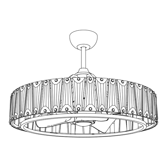
Odeon 33" Fandelight
w LED Bulbs
TM
Please consult a qualified electrician prior to install
Veuillez consulter un électricien qualifié pour suspendre le luminaire et le câblage.
Installation and safety instructions Read and save these instructions
Instructions d'installation et de sécurité lisez et sauvegardez ces instructions
Made in China | Fabrique en Chine | Hecho en China
1
Advertisement
Table of Contents

Related Manuals for Maxim Lighting Odeon Fandelight 61018


Summary of Contents for Maxim Lighting Odeon Fandelight 61018
- Page 1 Item/Model Num: 61018 Odeon 33" Fandelight w LED Bulbs Please consult a qualified electrician prior to install Veuillez consulter un électricien qualifié pour suspendre le luminaire et le câblage. Installation and safety instructions Read and save these instructions Instructions d'installation et de sécurité lisez et sauvegardez ces instructions Made in China | Fabrique en Chine | Hecho en China...
-
Page 2: Safety Precaution
SAFETY PRECAUTION • WARNING –To make sure power is off before attempting installation. • WARNING –Support Directly From Building Structure. When mounted directly to the building structure, appliance installation shall not expose combustible material and do not install the appliance to a ceiling with combustible finish. The installation of the appliance cannot leave the wood of the rafters or any thermal insulation exposed to the interior of the room. -
Page 3: Parts And Accessories
PARTS & ACCESSORIES Canopy Downrod Housing Mounting Bracket x1 Controller x 1 LED E12 Bulb x 8 Wall Remote Battery (included) Remote Mounting Plate Mounting Screw CR2032 Mounting Screws Expansion Bolt x 4 Self Tapping Screw &Washer x 4... -
Page 4: Fan Diagram
FAN DIAGRAM Screw (1) Lock Pin (2) Hanger Ball (3) Canopy (4) Canopy Ring (5) Coupling Cover (6) Downrod (7) Clevis Pin (8) Bolt (10) Nut (9) Spring Washer (11) Flat Washer (12) Coupling (14) Set Screws (13) Bulb (15) 8x4W LED Crystal (16) Screws (17) - Page 5 FAN ROD ASSEMBLY SECURING THE FAN ROD 1) Remove the Clevis Pin (8), Nut (9), Spring Washers (11), Flat Washers (12) & Bolt (10) on Coupling (14). 2) Loosen the Screw (1) from Hanger Ball (3), remove the Hanger Ball (3) and Lock Pin (2).
-
Page 6: Mounting The Bracket
MOUNTING THE BRACKET Outlet Box(3) Mounting Bracket (1) Mounting Screws (2) MOUNTING THE BRACKET SWITCH OFF THE ELECTRICAL MAINS AT THE CIRCUIT BREAKER FUSE BOX. 1) Install the mounting bracket (1) onto Outlet Box (3) with the Mounting Screws (2). WARNING - TO REDUCE THE RISK OF FIRE, ELECTRIC SHOCK, OR PERSONAL INJURY, MOUNT TO OUTLET BOX MARKED (ACCEPTABLE FOR FAN SUPPORT OF 15.9 KG (35LBS) OR LESS) AND USE MOUNTING... -
Page 7: Hanging The Fan
HANGING THE FAN Safety Wire Clamp HANGING THE FAN 1) Raise the fan and place the hanger ball onto mounting bracket. 2) Rotate the fan until the notch on hanger ball snapped into the slot on mounting bracket and sits firmly. NOTE : THE DOWNROD AND HANGER BALL SHOULD NOT ROTATE IF THIS STEP IS DONECORRECTLY. - Page 8 ELECTRICAL CONNECTIONS Controller MOLEX PLUG SWITCH OFF THE ELECTRICAL MAINS AT THE CIRCUIT BREAKER FUSE BOX. Connect the wire connector plugs correctly. The wire connector plugs design with fool proof device, please don’t force to plug. Otherwise it may affect the normal use of the light fan or burn the fan motor.
- Page 9 CANOPY INSTALL Controller Canopy Canopy Ring CANOPY INSTALL 1) Insert the controller into the space of the mounting bracket, and tidy up the wiring. 2) Carefully push the canopy to the bottom of the mounting bracket, make two sliding holes aligned to the two prominent screws on the mounting bracket, and then turn clockwise until tight.
-
Page 10: Remote Programming
REMOTE PROGRAMMING REMOTE SETTING (MODEL: FCT6000WT) 1) The battery is pre-installed and can be used by removing the insulation paper. Open the REMOTE battery cover and install DC3V battery (Model: CR2032) when replacing the battery. 2) Turn on the power of the light fan. 3) Within 30 sec after the “Beep”, press and hold the LEARN button for 3 sec. -
Page 11: Remote Functions
REMOTE FUNCTIONS REMOTE FUNCTION (MODEL: FCT6000WT) Operating Indicator Fan Speed Indicator (1~6) Timing Indicator (1, 3, 6hr) Turns off the fan Fan speed control (increasing) Fan speed control (decreasing) Timing the fan (Auto off after 1/3/6 hrs) Natural Wind: Fan speed changes within its range creating gentle natural wind effect. - Page 12 FORWARD/REVERSE FUNCTION Forward Reverse Fan rotates anti-clockwise creating Fan rotates clockwise creating an a downward airflow delivering a upward airflow of warm air moving cooling effect. from the ceiling. This function best at lower fan speeds. Used during hot weather for Better during cold weather to cooling air.
- Page 13 CLEANING & MAINTENANCE Due to the fan’s natural movement, connections may get loose after a period of usage. To ensure a proper and safety usage, inspect the suspension system and tighten all connections every 6 months. Caution there is a risk of shock! Disconnect from power source before assembling or cleaning.
-
Page 14: Fan Specifications
FAN SPECIFICATIONS 61018 580mm ≥1000mm 830mm Blade Volt Nett Gross Speed Watt Lamping Input weight weight 0.04 0.05 110- 0.08 8 x 4W 16.8 21.8 120V 0.12 60Hz 0.19 14.1 0.33 27.3 Specifications & measurements shown are subject to ±5% variations. - Page 15 ADDENDUM SPECIATY STRUCTURE INSTALLATION SPECIFIC MOUNTING PARTS KIT (NOT INCLUDED) MOUNTING BRACKET INSTALLATION INSTRUCTIONS SWITCH OFF ELECTRICAL MAINS AT THE CIRCUIT BREAKER FUSE BOX. CONCRETE CEILING 1) Use the Mounting Bracket (1) as a guide, mark the spots where the 4 Expansion Bolts (2) will be drilled.
- Page 16 SMART CONTROL ADD DEVICE MANUAL 1. Ensure the light fan that needs intelligent control can be used normally, and disconnect the power supply. 2. Make sure the Wi-Fi connected to the light fan is available and has normal Internet access. 3.
Need help?
Do you have a question about the Odeon Fandelight 61018 and is the answer not in the manual?
Questions and answers