Table of Contents
Advertisement
Advertisement
Table of Contents

Related Manuals for MSI Media Live


Summary of Contents for MSI Media Live
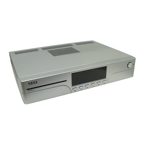
- Page 1 Media Live MS-6421 (V1.X) Media Center G52-64211X2...
- Page 2 Shielded interface cables and A.C. power cord, if any, must be used in order to comply with the emission limits. VOIR LA NOTICE D’INSTALLATION AVANT DE RACCORDER AU RESEAU. Media Live MS-6421 This device complies with Part 15 of the FCC Rules. Operation is subject to the...
-
Page 3: U.s. Patent Numbers
Trademark All trademarks are the properties of their respective owners. ® ® Intel and Pentium are registered trademarks of Intel Corporation. ® PS/2 and OS /2 are registered trademarks of International Business Machines Corporation. ® W indows 95/98/2000/NT/XP are registered trademarks of Microsoft Corporation. ®... -
Page 4: Safety Instructions
Safety Instructions Always read the safety instructions carefully. Keep this User’s Manual for future reference. Keep this equipment away from humidity. Lay this equipment on a reliable flat surface before setting it up. The openings on the enclosure are for air convection hence protects the equipment from overheating. - Page 5 Warning: 1. For every changes in powercord’s usage, please use an approved power cord with condition greater or equal to H05VV-F,3G , 0.75mm 2. Internal part is hazardous moving parts, please keep fingers and other body parts away. 3. For pluggable equipment, the socket-outlet shall be installed near the equipment and shall be easily accessible.
-
Page 6: Weee Statement
WEEE Statement... - Page 8 viii...
-
Page 9: Table Of Contents
CONTENTS FCC-B Radio Frequency Interference Statement ............ii Trademark ........................iii U.S. Patent Numbers ....................... iii Revision History ......................iii Safety Instructions ......................iv WEEE Statement ......................vi Chapter 1. Getting Started ..................1-1 Mainboard Specifications ................... 1-2 System Configuration ..................1-4 Front Panel .................... - Page 10 TV-Out Connector: JTV1 (Optional) ............2-16 Front Panel Connectors: JFP1 & JFP2 ............. 2-17 VGA Connector: JVGA2 ................2-17 Jumpers ......................2-18 Clear CMOS Jumper: JBAT1 ..............2-18 SCART Out Jumper: CN1 & CN2 (for SCART Out board) ......2-18 Slots ........................
- Page 11 Chapter 5. Software Setup ................... 5-1 Microsoft W indow XP Media Center ..............5-2 Setting Up ..................... 5-3 Getting Started ..................... 5-5 Play DVD ...................... 5-8 Online Spotlight .................... 5-9 My Videos ....................5-10 My Pictures ....................5-11 My Music ....................5-12 More Programs ...................
- Page 12 Installing the NVIDIA RAID Software Under W indows ......C-9 Initializing and Using the Disk Array ............C-10 NVRAID Management Utility ................C-12 Viewing RAID Array Configurations ............C-12 Setting Up a Spare RAID Disk ..............C-13 Morphing From One RAID Array to Another ..........C-17 Hot Plug Array ....................
-
Page 13: Chapter 1 Getting Started
Chapter 1 Getting Started Congratulations for purchasing Media Live (MS-6421) Media Center. This Media Live is your best Media Center choice. W ith the fantastic appearance and small form factor, it can easily be set anywhere. The feature packed platform also gives you an exciting Media Center... -
Page 14: Mainboard Specifications
SATA - Supports 4 SATA II ports by nVidia MCP51 ® (2 SATA II ports only for Media Live) - Supports storage and data transfers at up to 300 MB/s Floppy - 1 floppy port - Supports 1 FDD with 360K, 720K, 1.2M, 1.44M and 2.88Mbytes... - Page 15 Getting Started Connectors Back Panel - 3 Component Video Out (RGB) - 8 Audio RCA Out (for 8-channel audio support) - 1 Digital Video / Audio Out (HDMI) - 4 USB 2.0 Ports - 1 IEEE 1394 Port - 3 AV Out - 1 S-Video Out - 1 SCART Out - 1 VGA Out (D-Sub)
-
Page 16: System Configuration
MS-6421 Media Center System Configuration Front Panel 1. Microphone (Pink) 9. Rew Button 2. USB 2.0 Port 10. Fwd Button 3. IEEE 1394 Port 11. Skip Button 4. USB 2.0 Port 12. On / Standby 5. Headphone (Green) 13. Eject Button (for ODD) 6. -
Page 17: Back Panel
Getting Started Back Panel 1. Ventilation Hole 9. AV Out 2. Power Switch 10. S-Video Out 3. Power Jack (AC In) 11. SCART Out 4. Component Video Out 12. VGA Out (D-Sub) 5. Audio RCA Out 13. LAN Jack (RJ45) 6. -
Page 18: Chassis Design
MS-6421 Media Center Chassis Design - Dimension: 320mm (D) x 430mm (W) x 80mm (H) (with Bezel) - 3.5" Memory Card Reader with four slots supports MS(MS-Pro), CF/MD (CompactFlash I/II / Micro drive), SD/MMC, SM(SmartMedia) - Minimized screw structure - Detachable bay housing - Multiple ventilation holes Side Back... -
Page 19: System Picture
Getting Started System Picture Expansion slots M em ory Back Panel Socket Power Supply Driver Bay Front Panel Driver Bay x1 (for ODD) x2 (for HDD) -
Page 20: System Air Flow Direction
MS-6421 Media Center System Air Flow Direction Ventilation Hole Ventilation Hole Back Panel (for CPU Fan) (for Power Supply Fan) Ventilation Front Panel Ventilation Hole (for ODD) Hole (for HDD) After the installation is completed, please keep other objects away from the ventilation hole at least 2.5cm and above. -
Page 21: Remote Control
Getting Started Remote Control Remote Control Buttons (for European users) Play Stop Away Pause Fw d Replay Skip Back M or e Arr o w M edia Center CH / PG Volume M u te Recorded TV DVD Menu Guide Live TV 0-9, A-Z, #, * Teletext... -
Page 22: Remote Control Buttons (For Usa Users)
MS-6421 Media Center Remote Control Buttons (for USA users) Play Stop Away Pause Fw d Replay Skip Back M or e Arr o w M edia Center CH / PG Volume M u te Recorded TV DVD Menu Guide Live TV 0-9, A-Z, #, * Clear Enter... -
Page 23: Chapter 2 Hardware Setup
Chapter 2 Hardware Setup This chapter provides you with the information about hard ware s etup proc edures . W hil e doing the installation, be careful in holding the components and f ollow th e i ns t allation p roc edur es . For s ome components, if you install in the wrong orientation, the components will not work properly. -
Page 24: Mainboard Layout
MS-6421 Media Center Mainboard Layout JRCA3 CPU_FAN1 Winbond W83627EHG JRCA1 JVGA2 JTV1 HDMI1 JPW1 T: LAN jack B: USB ports nVidia C51PVG T: 1394 port B: USB ports PCI _E1 VSC8601XKN PCI _E2 nVidia BATT MCP51 PCI1 ALC883 VT6308P BIOS JCD1 JSPDI1 JSPDO1 JXPC1... -
Page 25: Cpu (Central Processing Unit)
Hardaware Setup CPU (Central Processing Unit) The mainboard supports AMD Athlon64 X2 / Athlon64 & Athlon FX processors. The ® mainboard uses a CPU socket called Socket AM2 (940-pin) for easy CPU installation. When you are installing the CPU, make sure the CPU has a heat sink and a cooling fan attached on the top to prevent overheating. -
Page 26: Memory
MS-6421 Media Center Memory The mainboard provides 4 slots for 240-pin non-ECC DDR2 400/533/667/800 DIMMs, which supports the memory size up to 4GB. Since DDR2 modules are not inter- changeable with DDR and the DDR2 standard is not backward compatible, you should always install DDR2 memory module in the DDR2 slot (DIMM1~DIMM4). -
Page 27: Power Supply
Hardaware Setup Power Supply The mainboard supports ATX power supply for the power system. Before inserting the power supply connector, always make sure that all components are installed properly to ensure that no damage will be caused. ATX 24-Pin Power Connector: JPWR1 This connector allows you to connect an ATX 24-pin power supply. -
Page 28: Atx 12V Power Connector: Jpw1
MS-6421 Media Center ATX 12V Power Connector: JPW1 This 12V power connector JPW 1 is used to provide power to the CPU. Pin Definition SIGNAL JPW1 Important 1. Make sure that all the connectors are connected to proper ATX power supplies to ensure stable operation of the mainboard. -
Page 29: Important Notification About Power Issue
Hardaware Setup Important Notification about Power Issue nForce chipset is very sensitive to ESD (Electrostatic Discharge), therefore this issue mostly happens while the users intensively swap memory modules under S5 (power- off) states, and the power code is plugged while installing modules. Due to several pins are very sensitive to ESD, so this kind of memory-replacement actions might cause system chipset unable to boot. -
Page 30: Front Panel
MS-6421 Media Center Front Panel The following illustration shows the Media Live front panel: Item Function Comments CD / DVD CD / DVD Player / Recorder. Eject Button Push the Eject Button to open / close. 7-in-1 Memory MS(MS-Pro), CF/MD(CompactFlash I/II / Card Reader Micro drive), SD/MMC, SM(SmartMedia). - Page 31 Hardaware Setup (Rewind) Moves the media backward. Rew Button (Fast-forward) Moves media forward. Fwd Button Moves media forward. Skip Button Integrated Media information display. VFD Module Power Button and LED. Press and hold button for seconds to On / Standby turn off.
-
Page 32: Back Panel
MS-6421 Media Center Back Panel The following illustration shows the Media Live back panel: Item Connector Type Left side: On Power Switch Right side: Off Power Jack AC 110-240V, (AC In) 50-60 Hz. Expansion Slot For expansion use only . - Page 33 Important 1. Media Live provides five different types of Video Output which includes 1) SCART Out 2) Component Video Out 3) VGA Out 4) AV Out 5) S- Video Out, please select only one type to use at a time.
-
Page 34: Connectors
MS-6421 Media Center Connectors Floppy Disk Drive Connector: FDD1 This standard FDD1 connector supports 360K, 720K, 1.2M, 1.44M and 2.88M floppy disk types. FDD1 ATA133 Hard Disk Connectors: IDE1 & IDE2 The mainboard has a 32-bit Enhanced PCI IDE and Ultra DMA 66/100/133 controller that provides PIO mode 0~4, Bus Master, and Ultra DMA 66/100/133 function. -
Page 35: Serial Ata Ii Connectors: Sata1~Sata4
SATA1~SATA4 are high-speed SATA II interface ports. Each supports data rates of 300 MB/s and is fully compliant with Serial ATA specifications. Each Serial ATA connector can connect to 1 hard disk device. (For Media Live, 2 SATA II ports can be used only because of the ME assembly status.) -
Page 36: Fan Power Connectors: Cpu_Fan1 & Sysfan1
MS-6421 Media Center Fan Power Connectors: CPU_FAN1 & SYSFAN1 The fan power connectors support system cooling fan with +12V. W hen connecting the wire to the connectors, always take note that the red wire is the positive and should be connected to the +12V, the black wire is Ground and should be connected to GND. -
Page 37: Cd-In Connector: Jcd1
Hardaware Setup CD-In Connector: JCD1 This connector is provided for CD-ROM audio. JCD1 Front USB Connectors: JUSB1 & JUSB2 The mainboard provides USB 2.0 pinheaders (optional USB 2.0 bracket available) that are compliant with Intel® I/O Connectivity Design Guide. USB 2.0 technology increases data transfer rate up to a maximum throughput of 480Mbps, which is 40 times faster than USB 1.1, and is ideal for connecting high-speed USB interface peripherals such as USB HDD, digital cameras, MP3 players, printers, modems and the like. -
Page 38: Spdif-Out/In Connectors: Jspdo1 & Jspdi1 (Spdif-In Is Optional)
MS-6421 Media Center SPDIF-Out/In Connectors: JSPDO1 & JSPDI1 (SPDIF-In is Optional) These connectors are used to connect SPDIF (Sony & Philips Digital Interconnect Format) interface for digital audio transmission. The JSPDO1 is for SPDIF-Out and the JSPDI1 is for SPDIF-In. SPDIF SPDIF JSPDO1... -
Page 39: Vga Connector: Jvga2
Hardaware Setup Pin Definition SIGNAL DESCRIPTION Ground Speaker Power SPK- Speaker- SLED Suspend LED BUZ+ Buzzer+ JFP2 PLED Power LED BUZ- Buzzer- No connection SPK+ Speaker+ VGA Connector: JVGA2 The connector is provided for VGA monitors. Pin Definition SIGNAL SIGNAL VGA_R DDC_DATA VGA_G... -
Page 40: Jumpers
MS-6421 Media Center Jumpers The motherboard provides the following jumpers for you to set the computer’s function. This section will explain how to change your motherboard’s function through the use of jumpers. Clear CMOS Jumper: JBAT1 There is a CMOS RAM onboard that has a power supply from external battery to keep the data of system configuration. -
Page 41: Slots
Hardaware Setup Slots PCI (Peripheral Component Interconnect) Express Slot PCI Express architecture provides a high performance I/O infrastructure for Desktop Platforms with transfer rates starting at 2.5 Giga transfers per second over a PCI Express x1 lane for Gigabit Ethernet, TV Tuners, 1394 controllers, and general purpose I/O. -
Page 42: Pci (Peripheral Component Interconnect) Slots
MS-6421 Media Center PCI (Peripheral Component Interconnect) Slot The PCI slot supports LAN cards, SCSI cards, USB cards, and other add-on cards that comply with PCI specifications. At 32 bits and 33 MHz, it yields a throughput rate of 133 MBps. -
Page 43: Chapter 3. Sy Stem Assembly
System Assembly Chapter 3 System Assembly This chapter provides you with the information about sys- tem assembly procedures. W hile doing the installation, be careful in holding the components and follow the installation procedures. Use a grounded wrist strap before handling computer components. -
Page 44: Overview
MS-6421 Media Center Overview The built-in mainboard is designed for Media Live only. Except the mainboard, the built- in components of the barebone include Power Supply and 8 other cards. In this chapter we’ll show you how to install Optical Disk Drive(ODD), Hard Disk Drive(HDD), PCI Card, CPU, CPU Cooler and Memory Modules. -
Page 45: Packing Checklist
System Assembly Packing Checklist Before assembling your system, please check the items listed below for basic system operation. CPU Cooler CPU (Optional) Optical Disk Drive (Optional) Hard Disk Drive (Optional) Memory M odule (Optional) PCI Card (Optional) *These pictures are for your reference only. Your packing contents may vary depending on the model you purchased. -
Page 46: Installation Procedures
MS-6421 Media Center Installation Procedures 1. Removing Top Cover Unlock the four screws (screw type 1) on the back panel with a screwdriver. Follow the direction arrows to slide the top cover off and then remove it by lift it up carefully with hands. - Page 47 System Assembly Follow the direction arrow to pull the three hooks open to remove the front panel and to release all the cages. Important 1. Always be careful when you handle with the three hooks on the front panel. Remember to pull them open gently with fingers or the damages can be made easily.
-
Page 48: Installing Hard Disk Driver
MS-6421 Media Center 2. Installing Hard Disk Driver (HDD) Unlock the two screws (screw type 1) on the front panel with a screwdriver. Follow the direction arrow to take out the HDD holder carefully with hands. Always keep your fingers away from thes e two sharp edges of the HDD holder or you may get hurt easily. - Page 49 System Assembly Follow the direction arrow to insert the HDD into the HDD holder carefully and then lock up the two screws (screw type 1) with a screwdriver. Install the HDD holder (with HDD) onto the chassis carefully and connect the power cable.
-
Page 50: Installing Optical Disk Driver
MS-6421 Media Center 3. Installing Optical Disk Driver (ODD) Unlock the two screws (screw type 1) on the front panel with a screwdriver. Follow the direction arrow to push the ODD tray forward carefully with hands. Insert the ODD interface board into the slim slot-in ODD and please avoid touch- ing the pinheader on the board because Important... - Page 51 System Assembly Lock up the two screws (screw type 2) on the O DD interf ac e board with a screwdriver. Match the orientation of ODD and ODD tray and then follow the direction ar- row to install the ODD onto the ODD tray carefully.
- Page 52 MS-6421 Media Center Connect the power cable. Connect the IDE cable. Lock back the two screws (screw type 1) on the front panel with a screwdriver. 3-10...
-
Page 53: Installing Pci Card
System Assembly 4. Installing PCI Card Unlock the screw (screw type 1) on the lock bracket with a screwdriver. Follow the direction arrow to open the lock bracket with fingers carefully. Remove the iron shield to release the PCI expansion slot. 3-11... - Page 54 MS-6421 Media Center Insert the PCI card vertically into the PCI slot. Follow the direction arrow to close the lock bracket with fingers carefully. Lock back the screw (screw type 1) on the back panel with a screwdriver. 3-12...
-
Page 55: Installing Cpu
System Assembly 5. Installing CPU Pull the lever sideways away from the CPU socket, make sure you lift it up to a 90 degree angle. Find the gold arrow on the AMD ® CPU before installation, remember the C P U c an on l y f it i n t h e c or r ec t orientation. -
Page 56: Installing Cpu Cooler
MS-6421 Media Center 5. Installing CPU Cooler Connect the power cable of CPU cooler first. Match the direction of CPU cooler and mainboard retention module. I n s t al l th e C P U c ool er on t o t h e mainboard retention frame by press- ing the black holder down firmly with a screwdriver and then close the silver... -
Page 57: Installing Memory Modules
System Assembly 6. Installing Memory Modules Open the plastic clips at each side. The DDR2 memory module has only one notch on the center of module and it will only fit in the correct orientation. Notch Golden finger Insert the memory module vertically into the slot by pushing it in until the golden finger is deeply inserted in the slot. -
Page 58: 10. Restoring Top Cover
MS-6421 Media Center 10. Restoring Top Cover Follow the direction arrow to restore the front panel to the chassis to fix all the cages. Follow the direction arrows to restore the top cover. Push forward Lock back the four screws (screw type 1) on the back panel with a screwdriver. -
Page 59: Chapter 4. Bios Setup
BIOS Setup Chapter 4 BIOS Setup This chapter provides the information on the BIOS Setup program and allows you to configure the system for opti- mum use. You may need to run the Setup program when: An error message appears on the screen during the system booting up, and requests you to run SETUP. -
Page 60: Entering Setup
MS-6421 Media Center Entering Setup Power on the computer and the system will start POST (Power On Self Test) process. W hen the message below appears on the screen, press <DEL> key to enter Setup. Press DEL to enter SETUP If the message disappears before you respond and you still wish to enter Setup, restart the system by turning it OFF and On or pressing the RESET button. -
Page 61: Control Keys
BIOS Setup Control Keys < > Move to the previous item < > Move to the next item < > Move to the item in the left hand < > Move to the item in the right hand <Enter> Select the item <Esc>... -
Page 62: The Main Menu
MS-6421 Media Center The Main Menu Standard CM OS Features Use this menu for basic system configurations, such as time, date etc. Advanced BIOS Features Use this menu to setup the items of AMI special enhanced features. ® Advanced Chipset Features Use this menu to change the values in the chipset registers and optimize your system’s performance. - Page 63 BIOS Setup H/W M onitor This entry shows your PC health status. Load Optimized Defaults Use this menu to load the default values set by the mainboard manufacturer specifi- cally for optimal performance of the mainboard. BIOS Setting Password Use this menu to set the password for BIOS. Save &...
-
Page 64: Standard Cmos Features
MS-6421 Media Center Standard CMOS Features Date (MM:DD:YY) This allows you to set the system to the date that you want (usually the current date). The format is <day> <month> <date> <year>. [Day] Day of the week, from Sun to Sat, determined by BIOS. Read only. [Month] The month from Jan. - Page 65 BIOS Setup Primary/Secondary IDE Master/Slave, SATA0/1 Primary/Secondary Channel. Press <+> or <-> to select [Manual], [None] or [Auto] type. Note that the specifications of your drive must match with the drive table. The hard disk will not work properly if you enter improper information for this category.
- Page 66 MS-6421 Media Center Floppy Drive A This item allows you to set the type of floppy drives installed. Halt On The setting determines whether the system will stop if an error is detected at boot. W hen the system stops for the errors preset, it will halt on for 15 seconds and then automatically resume its operation.
-
Page 67: Advanced Bios Features
BIOS Setup Advanced BIOS Features Quick Boot Setting the item to [Enabled] allows the system to boot within 5 seconds since it will skip some check items. Boot Up Num-Lock LED This setting is to set the Num Lock status when the system is powered on. Setting to [On] will turn on the Num Lock key when the system is powered on. - Page 68 MS-6421 Media Center MPS Table Version This field allows you to select which MPS (Multi-Processor Specification) version to be used for the operating system. You need to select the MPS version supported by your operating system. To find out which version to use, consult the vendor of your operating system.
- Page 69 BIOS Setup Hard Disk Drives Press <Enter> to enter the sub-menu. Then you may use the arrow keys ( ) to select the desired device, then press <+>, <-> key to move it up/down in this hard disk drives list. Removable Boot Priority Press <Enter>...
-
Page 70: Advanced Chipset Features
MS-6421 Media Center Advanced Chipset Features OnChip and PCIe VGA selection This item allows you to select OnChip or PCI Express VGA display. Available setting options are: [Auto] Display only OnChip or PCI Express VGA. [Both] Display both OnChip and PCI Express VGA. OnChip VGA Frame Buffer Size The field specifies the size of system memory allocated for video memory. -
Page 71: Integrated Peripherals
BIOS Setup Integrated Peripherals USB Controller Select [Enabled] if your system contains a Universal Serial Bus (USB) controller and you have USB peripherals. USB Device Legacy Support Set to [Auto] if you need to use any USB 1.1/2.0 device in the operating system that does not support or have any USB 1.1/2.0 driver installed, such as DOS and SCO Unix. - Page 72 MS-6421 Media Center Azalia Audio Azalia is the codename of “High Definition Audio.” This setting allows users to dis- able/enable the High Definition Audio interface integrated in southbridge. On-Chip ATA Devices Press <Enter> to enter the sub-menu: PCI IDE BusM aster Set this option to [Enabled] to specify that the IDE controller on the PCI local bus has bus mastering capability.
- Page 73 BIOS Setup I/O Devices Press <Enter> to enter the sub-menu: OnBoard Floppy Controller Select [Enabled] if your system has a floppy disk controller (FDD) installed on the system board and you wish to use it. If you install add-on FDC or the system has no floppy drive, select [Disabled] in this field.
-
Page 74: Power Management Setup
MS-6421 Media Center Power Management Setup ACPI Function This item is to activate the ACPI (Advanced Configuration and Power Management Interface) Function. If your operating system is ACPI-aware, such as Windows 98SE/ 2000/ME, select [Enabled]. ACPI Standby State This item specifies the power saving modes for ACPI function. If your operating system supports ACPI, such as W indows 98SE, W indows ME and W indows 2000, you can choose to enter the Standby mode in S1 (POS) or S3 (STR) fashion through the setting of this field. - Page 75 BIOS Setup Power Button Function This feature allows users to configure the Power Button function. Settings are: [On/Off] The power button functions as a normal power-on/-off button. [Suspend] W hen you press the power button, the computer enters the suspend/sleep mode, but if the button is pressed for more than four seconds, the computer is turned off.
-
Page 76: Pnp/Pci Configurations
MS-6421 Media Center PNP/PCI Configurations Primary Graphics Adapter This setting specifies which graphic card is your primary graphics adapter. Select [PCI], the system initializes the installed PCI VGA card first. If a PCI VGA card is not available, it will initialize the PCI Express card. PCI Latency Timer This item controls how long each PCI device can hold the bus before another takes over. - Page 77 BIOS Setup IRQ Resource Setup The items are adjustable only when Resources Controlled By is set to Manual. Press <Enter> and you will enter the sub-menu of the items. IRQ Resources list IRQ 3/4/5/7/ 9/10/11/12/14/15 for users to set each IRQ a type depending on the type of device using the IRQ.
-
Page 78: H/W Monitor
MS-6421 Media Center H/W Monitor Spread Spectrum W hen the motherboard’s clock generator pulses, the extreme values (spikes) of the pulses creates EMI (Electromagnetic Interference). The Spread Spectrum function reduces the EMI generated by modulating the pulses so that the spikes of the pulses are reduced to flatter curves. - Page 79 BIOS Setup CPU Spread Specturm This setting is used to enable or disable the CPU Spread Spectrum feature. W hen overclocking the CPU, always set it to [Disabled]. Setting options: [Disabled], [Center Spread] and [Down Spread]. C51 PCIE Spread Specturm This setting is used to enable or disable the C51 PCI Express Spread Spectrum feature.
- Page 80 MS-6421 Media Center Cool’n’Quiet This feature is especially designed for AMD Athlon processor, which provides a CPU temperature detecting function to prevent your CPU’s from overheating due to the heavy working loading. Important To ensure the stability of the Cool'n'Quiet function, it is always recom- mended to have the memories plugged in DIMM1.
-
Page 81: Load Optimized Defaults
BIOS Setup Load Optimized Defaults The Optimized Defaults are the default values set by the mainboard manufacturer specifically for optimal performance of the mainboard. W hen you select Load Optimized Defaults, a message as below appears: Pressing Y loads the default factory settings for optimal system performance. 4-23... -
Page 82: Bios Setting Password
MS-6421 Media Center BIOS Setting Password W hen you select this function, a message as below will appear on the screen: Type the password, up to 6 characters in length, and press <Enter>. The password typed now will replace any previously set password from CMOS memory. You will be prompted to confirm the password. -
Page 83: Chapter 5. Software Setup
Chapter 5 Software Setup This chapter provides you with the software information about Media Live (MS-6421) Media Center. With a full range of easy-to-use digital entertainment features, experience TV, movies, music and photos with Media Live are like never before. -
Page 84: Microsoft W Indow Xp Media Center
MS-6421 Media Center ® ® Microsoft Windows Media Center... -
Page 85: Setting Up
Software Setup Setting Up The first time you start your Media Live, a Media Center Setup Wizard opens. It is best to complete each step in the setup wizard to be able to use all the features in Media Center. The Media Center Setup W izard may take approximately 10-40 minutes to complete. - Page 86 MS-6421 Media Center Listed below are some of the items included in the M edia Center Setup Wizard: Check for the Internet connection An Internet connection allows your Media Center to update and download the TV Program Guide and to display the information of your music CDs and other media. Important It is necessary to subscribe with and Internet Service Provider (ISP) to have an Internet connection.
-
Page 87: Getting Started
The Media Live is set up correctly. The remote control has two AA 1.5V alkaline batteries installed. The Media Live has a properly configured and working Internet connection. The Media Live is properly connected to your TV signal source. Opening the Media Center 1. - Page 88 Media Center Start Menu Overview Enter the menu to exit Media Center, to turn off or to restart the Media Live, to log off and to end up your Media Center, to put the Media Live into standby mode, or to switch users.
- Page 89 Software Setup Toolbar: Here you can use media playback control includes play, stop, pause, skip, fast-forward, replay, rewind, record, volume up/down and channel up/ down. Play DVD: Here you can watch your DVD movies. Online Spotlight: Here you can link to the Media Center official website for more offers and services.
-
Page 90: Play Dvd
MS-6421 Media Center Play DVD In the Media Center Play DVD window, you can control the playback with your remote control. But if you play your DVD in another media program, the remote control will not be able to use. 1. -
Page 91: Online Spotlight
Software Setup Online Spotlight Online Spotlight contains links to the Media Center information, offers and services. 1. Press the Media Center Green Start Button on the remote control. 2. Select Online Spotlight on the main menu to start. Click here In Online Spotlight you can: M usic This item includes links to music service providers such as Napster and Live365. -
Page 92: My Videos
MS-6421 Media Center My Videos In the Media Center My Videos window, you can play your home video files you created and video files you downloaded from the Internet. 1. Press the Media Center Green Start Button on the remote control. 2. -
Page 93: My Pictures
Software Setup My Pictures In the Media Center My Pictures window, you can view and print your pictures from the folders you created in the My Pictures directory of W indows Explorer. In fact, My Pictures is a folder on your hard disk drive (HDD) in the My Documents folder. It is also a Media Center menu item that allows you to view and to search for your digital images by using the remote control or the keyboard and mouse. -
Page 94: My Music
MS-6421 Media Center My Music In the Media Center My Music window, you can copy your digital music files and organize a music library. In fact, My Music in Media Center is designed to work with the Windows Media Player program. That means, music files that are added from My Music in Media Center are copied into the Windows Media Player Library and are accessible from Media Center. -
Page 95: More Programs
Software Setup More Programs More Programs contains links to programs, services and common tasks. 1. Press the Media Center Green Start Button on the remote control. 2. Select More Programs on the main menu to start. Click here In More Programs you can: Creat CD / DVD This item includes a link to a CD creation wizard that helps you find the media files you want to copy to CD or DVD. -
Page 96: Settings
MS-6421 Media Center Settings In the Media Center Settings window, you can change settings for watching TV, for viewing pictures and slide shows, for controlling sound and for the display of all the Media Center windows. 1. Press the Media Center Green Start Button on the remote control. - Page 97 Software Setup Important Some settings such as “Parental Control” and “Caption Display” set- tings for TV and DVDs are included with select models only. Not all channels support closed captioning. Pictures Here you can set up slide show settings. M usic Here you can select visualizations or song information to display when playing music.
- Page 98 MS-6421 Media Center Parental Controls - Here you can block unwanted TV channels and block unwanted TV and movie ratings, change access code and reset parental controls. Automatic Downloads Options - Here you can get media information about CDs, DVDs and movies from the Internet and to select HOW to down load the TV Program Guide.
-
Page 99: My Tv
Software Setup My TV In the Media Center My TV window, you can watch Live TV and record your favorite shows. Just use the TV Program Guide to find the show you want to watch and record. From the My TV window, you can also search and play your favorite TV s hows . -
Page 100: Radio
MS-6421 Media Center Radio Media Center can play FM readio if your MediaLive is equipped with a radio tuner input. In the Media Center Radio window, you can play FM radio stations by using your rmote control. 1. Press the Media Center Green Start Button on the remote control. -
Page 101: Microsoft W Indow Vista Media Center
Software Setup ® ® Microsoft Windows Vista Media Center 5-19... -
Page 102: Overview
MS-6421 Media Center Overview ® Vista Media Center can handle a variety of multimedia content. You can Windows watch live or recorded TV, listen to digital music, view pictures and personal videos, play games, burn CDs and DVDs, listen to FM and Internet radio stations, or access content from online services. -
Page 103: How To Use
Software Setup How To Use To better understand how Window Media Center works, you can learn more from the following: W atch TV (Page 5-22) Record TV (Page 5-23) Play video and watch pictures (Page 5-24) Listen to music (Page 5-25) Play your digital media anywhere in the home (Page 5-26 &... - Page 104 MS-6421 Media Center Watch TV You can use Windows Media Center to watch TV and movies. You can also choose to pause live TV so that you can do other things without missing parts of your favorite TV shows. W hen you pause live TV or a movie, the TV show or movie that is currently playing is temporarily recorded as a video file.
- Page 105 Software Setup Record TV You can use Windows Media Center to record live TV and movies. W hen you record a TV show or movie, the TV show that you record is saved as a Microsoft Recorded TV show with a .dvr-ms file name extension. Important Windows Media Center allows you to easily rip, burn, store and orga- nize your personal music, videos, pictures and recorded TV programs.
- Page 106 MS-6421 Media Center Play video and watch pictures You can watch pictures in a slide show and play videos using Windows Media Center. You can use different search criteria to find digital media files such as movies, videos, music, pictures, or recorded TV shows. These files are stored in libraries on your Windows Media Center computer.
- Page 107 Software Setup Listen to music You can use Windows Media Center to play music, queue songs up to play, or create playlists of your favorite music. If you want, you can also choose to play music while viewing your favorite pictures that appear in a slide show. The title Music includes four items - music library, play all, radio and search.
- Page 108 MS-6421 Media Center Play your digital media anywhere in the home Windows Media Center lets you enjoy TV, digital music, pictures, and video on your Windows Media Center computer. With a Windows Media Center Extender, you can bring the Windows Media Center experience out of the living room and extend it into any other room of the house.
- Page 109 Software Setup W atch or record TV shows You can watch or record all your favorite shows by using Media Center Extender. You can record all the shows in a series, shows that feature a favorite actor, and more. Although you can watch the recorded shows on the Media Center Extender, the recorded TV files are still stored on the Windows Media Center computer.
- Page 110 MS-6421 Media Center Listen to radio You can use Windows Media Center to listen to FM and Internet radio stations available in your area, and you can create presets for your favorite radio stations. Use the on-screen transport controls in the bottom right of the screen to control playback, including changing channels, adjusting volume, and pausing or stopping playback.
- Page 111 Software Setup Play a CD or DVD Using Windows Media Center, you can play audio and data CDs, as well as video and data DVDs. This lets you enjoy both commercial CDs and DVDs, as well as CDs and DVDs that you have created. To play DVDs, you must have a DVD drive and a compatible DVD decoder installed on your computer.
-
Page 112: Play Games
MS-6421 Media Center Browse, stream, and download digital media from Online Me- Windows Media Center offers a number of partner programs in Online Media to en- hance your entertainment experience. For example, you can play games on demand, share pictures, find digital music and radio programs, download movies, and watch videos over the Internet. -
Page 113: Remote Control
Software Setup Remote Control The remote control is designed to work with Media Live. You can use your remote control with MdeiaLive to play CDs and DVDs, to view pictures, and to watch and record television programs. This remote control helps you navigate the MediaLive windows on your computer just as a TV remote control helps you navigate cable TV options or control the playback of a movie in a VCR or DVD player. - Page 114 MS-6421 Media Center Media Center Remote Control Buttons Overview (Description and location may vary) * Function will shown in the red / green / yellow / blue area at the bottom of screen. The information provided varies based on your area and television network. 5-32...
- Page 115 Software Setup The following description shows the Media Center remote control buttons. LED: Activity indicator lights on pressing a button. Away: Puts the MediaLive into and out of a Power Reduced Away Mode. It does s not turn the MediaLive off. Play: Plays the selected media.
- Page 116 MS-6421 Media Center OK: Selects the desired action or window option. It acts as the Enter Key. . Media Center: Opens Media Center to the main menu. Volume: Increase (+) and decrease (-) sound. CH / PG: Up (+) and down (-) change the TV channel or move pages up and down, depending on available options.
- Page 117 Important If you turn off your Media Live, it will not record any scheduled TV program. The Media Live must be turned on or be in standby mode to record TV programs.
-
Page 118: Installing The Remote Control Batteries
MS-6421 Media Center Installing the Remote Control Batteries 1. Open up the battery cover from the back of the remote control. 2. Insert two AA 1.5V alkaline batteries. (provided) 3. Replace the battery cover. 4. Test the remote control by pressing any key. The indicator light should blink. Battery Con- tainer IECR06/AA/UM-3/1.5V... -
Page 119: Appendix A Realtek Alc883 Audio
Realtek ALC883 Audio Appendix A Realtek ALC883 Audio The Realtek ALC883 provides 10-channel DAC that simul- taneously supports 7.1 sound playback and 2 channels of independent stereo s ound output (multiple streaming) through the Front-Out-Left and Front-Out-Right channels. -
Page 120: Installing The Realtek Hd Audio Driver
MS-6421 Media Center Installing the Realtek HD Audio Driver You need to install the driver for Realtek ALC883 codec to function properly before you can get access to 2-, 4-, 6-, 8- channel or 7.1+2 channel audio operations. Follow the procedures described below to install the drivers for different operating systems. - Page 121 Realtek ALC883 Audio 3. Click Next to install the Realtek High Definition Audio Driver. Click here 4. Click Finish to restart the system. Select this option Click here...
-
Page 122: Software Configuration
MS-6421 Media Center Software Configuration After installing the audio driver, you are able to use the 2-, 4-, 6- or 8- channel audio feature now. Click the audio icon from the system tray at the lower-right corner of the screen to activate the HD Audio Configuration. It is also available to enable the audio driver by clicking the Azalia HD Sound Effect M anager from the Control Panel. -
Page 123: Sound Effect
Realtek ALC883 Audio Sound Effect Here you can select a sound effect you like from the Environment list. Environment Simulation You will be able to enjoy different sound experience by pulling down the arrow, totally 23 kinds of sound effect will be shown for selection. Realtek HD Audio Sound Manager also provides five popular settings “Stone Corridor”, “Bathroom”, “Sewer pipe”, “Arena”... - Page 124 MS-6421 Media Center Equalizer Selection Equalizer frees users from default settings; users may create their owned preferred settings by utilizing this tool. 10 bands of equalizer, ranging from 100Hz to 16KHz. Save Reset T h e s e t t i n g s a r e 10 bands of equalizer saved permanently...
- Page 125 Realtek ALC883 Audio Frequently Used Equalizer Setting Realtek recognizes the needs that you might have. By leveraging our long experience at audio field, Realtek HD Audio Sound Manager provides you certain optimized equal- izer settings that are frequently used for your quick enjoyment. [How to Use It] Other than the buttons “Pop”...
-
Page 126: Mixer
MS-6421 Media Center Mixer In the Mixer part, you may adjust the volumes of the rear and front panels individually. 1. Adjust Volume You can adjust the volume of the speakers that you pluged in front or rear panel. Important Before set up, please make sure the playback devices are well plugged in the jacks on the rear or front panel. - Page 127 Realtek ALC883 Audio Select this option Click here W hen you are playing the first audio source (for example: use W indows Media Player to play DVD/VCD), the output will be played from the rear panel, which is the default setting. Then you must to select the Realtek HD Audio 2nd output from the scroll list first, and use a different program to play the second audio source (for example: use Winamp to play MP3 files).
- Page 128 MS-6421 Media Center 3. Playback control Playback device Tool Mute This function is to let you freely decide which ports to output the sound. And this is essential when multi-streaming playback enabled. - Realtek HD Audio Output - Realtek HD Audio 2nd Output M u te You may choose to mute single or multiple volume controls or to completely mute sound output.
- Page 129 Realtek ALC883 Audio 4. Recording control Tool Mute Recording device -Realtek HD Digital input -Realtek HD Audio input M u te You may choose to mute single or multiple volume controls or to completely mute sound input. Tool - Show the following volume controls This is to let you freely decide which volume control items to be displayed.
-
Page 130: Audio I/O
MS-6421 Media Center Audio I/O In this tab, you can easily configure your multi-channel audio function and speakers. You can choose a desired multi-channel operation here. a. Headphone for the common headphone b. 2CH Speaker for Stereo-Speaker Output c. 4CH Speaker for 4-Speaker Output d. - Page 131 Realtek ALC883 Audio Connector Settings Click to access connector settings. Disable front panel jack detection (option) Jack detection function only works with HD audio front panel. M ute rear panel output when front headphone plugged in. Enable auto popup dialogue, when device has been plugged in Once this item checked, the dialog “Connected device”...
- Page 132 MS-6421 Media Center S/PDIF Short for Sony/Philips Digital Interface, a standard audio file transfer format. S/PDIF allows the transfer of digital audio signals from one device to another without having to be converted first to an analog format. Maintaining the viability of a digital signal prevents the quality of the signal from degrading when it is converted to analog.
- Page 133 Realtek ALC883 Audio Test Speakers You can select the speaker by clicking it to test its functionality. The one you select will light up and make testing sound. If any speaker fails to make sound, then check whether the cable is inserted firmly to the connector or replace the bad speakers with good ones.
-
Page 134: Microphone
MS-6421 Media Center Microphone In this tab you may set the function of the microphone. Select the Noise Suppres- sion to remove the possible noise during recording, or select Acoustic Echo Cancelltion to cancel the acoustic echo druing recording. Acoustic Echo Cancelltion prevents playback sound from being recorded by mi- crophone together with your sound. -
Page 135: 3D Audio Demo
Realtek ALC883 Audio 3D Audio Demo In this tab you may adjust your 3D positional audio before playing 3D audio applica- tions like gaming. You may also select different environment to choose the most suitable environment you like. A-17... -
Page 136: Information
MS-6421 Media Center Information In this tab it provides some information about this HD Audio Configuration utility, including Audio Driver Version, DirectX Version, Audio Controller & Audio Codec. You may also select the language of this utility by choosing from the Language list. Also there is a selection Show icon in system tray. -
Page 137: Hardware Setup
Realtek ALC883 Audio Hardware Setup Connecting the Speakers W hen you have set the Multi-Channel Audio Function mode properly in the software utility, connect your speakers to the correct phone jacks in accordance with the setting in software utility. n 2-Channel M ode for Stereo-Speaker Output Refer to the following diagram and caption for the function of each phone jack on the back panel when 2-Channel Mode is selected. - Page 138 MS-6421 Media Center n 4-Channel M ode for 4-Speaker Output Description: Connec t two s p eakers to bac k panel’s Front-channel Line Out con- nector and two speakers to the Rear- channel Line Out connector. 4-Channel Analog Audio Output Line Out (Side surround channels) Right.
- Page 139 Realtek ALC883 Audio n 6-Channel M ode for 6-Speaker Output Description: Connect two speakers to back panel’s Front-channel Line Out connector, two speakers to the Rear-channel Line out connector and two speakers to the Center/ S ub woof er -c hann el L in e O u t connector.
- Page 140 MS-6421 Media Center n 8-Channel M ode for 8-Speaker Output Description: Connect two speakers to back panel’s Front-channel Line Out connector, two speakers to the Rear-channel Line out connector, t wo s peakers t o t he Cent er / Subwoofer-channel Line Out con- nector and two speakers to the Side-channel Line Out connector.
-
Page 141: Appendix Btv-Out Function
TV-Out Function Appendix B TV-Out Function You need to install the TV-Out bracket before you can get access to the TV-out function. Follow the procedures de- scribed later to configure the display settings. -
Page 142: Display Setup
MS-6421 Media Center Display Setup The following procedures describe display setup using W indows XP. W indows 2000 screens are slightly different but the procedures are the same as described. To enable the TV-Out function, follow this procedure: 1. Restart the computer. After enter- ing the Windows OS, left-click in the window and the screen will pop up a menu. - Page 143 TV-Out Function 4. In the nView Display Settings field, choose the current display and display mode. 5. In the Device Settings, select the TV format.
- Page 144 MS-6421 Media Center If you have a TV connected and it is not being detected, you can check the “Force TV detection” box in the Tools field. Important Please note that the TV-out function can not work with the onboard D- Sub out function that is to say, you can not use the TV-out function and the onboard D-Sub out function simultaneously.
-
Page 145: Appendix C Nvidia Raid
nVidia RAID Appendix C nVidia RAID NVIDIA brings Redundant Array of Independent Disks (RAID) technology—which is used by the world’s leading businesses—to the common PC desktop. This technology uses multiple drives to either increase total disk space or to offer data protection. For all levels, RAID techniques optimize storage solutions by using multiple disks grouped together and treating them as a single storage resource. -
Page 146: Introduction
MS-6421 Media Center Introduct ion System Requirement Operating System Support NVRAID supports the following operating systems: W indows XP/ 2000 RAID Arrays NVRAID supports the following types of RAID arrays described in this section: RAID 0: RAID 0 defines a disk striping scheme that improves the disk read and write times for many applications. -
Page 147: Raid Configuration
nVidia RAID RAID Configuration Basic Configuration Instructions The following are the basic steps for configuring NVRAID: Non-Bootable RAID Array 1. Choose the hard disks that are to be RAID enabled in the system BIOS. (To enable the SATA 0/ 1 Primary/ Secondary Channel in On-Chip ATA Devices of Integrated Peripherals in BIOS.) 2. - Page 148 MS-6421 Media Center Understanding the “Define a New Array” Window Use the Define a New Array window to • Select the RAID Mode • Set up the Striping Block • Specify which disks to use for the RAID Array Depending on the platform used, the system can have one or more channels. In a typical system there is usually one controller and multiple channels, and each chan- nel has a slave and a master.
- Page 149 nVidia RAID Using the Define a New Array Window If necessary, press the tab key to move from field to field until the appropriate field is highlighted. • Selecting the RAID Mode By default, this is set to [Mirroring]. To change to a different RAID mode, press the down arrow key until the mode that you want appears in the RAID Mode box—either [Mirroring], [Striping], [RAID5], [Spanning], or [Stripe Mirroring].
- Page 150 MS-6421 Media Center Completing the RAID BIOS Setup 1. After assigning your RAID array disks, press F7. The Clear disk data prompt appears. 2. Press Y if you want to wipe out all the data from the RAID array, otherwise press N.
-
Page 151: Installing The Raid Driver (For Bootable Raid Array
Please follow the instruction below to make an nVIDIA Serial ATA RAID driver for yourself. 1. Insert the MSI CD into the CD-ROM drive. 2. Click the “Browse CD” on the Setup screen. 3. Copy all the contents in the :\\nVidia \System \MCP55 \IDE \Win XP\sataraid to a formatted floppy disk. - Page 152 MS-6421 Media Center 4. Press Enter to continue with W indows XP Installation. Be sure to leave the floppy disk inserted in the floppy drive until the blue screen portion of W indows XP installation is completed, then take out the floppy. 5.
-
Page 153: Nvidia Ide Driver/ Raid Utility Installation
nVidia RAID NVIDIA IDE Driver/ RAID Utility Installation Installing the NVIDIA RAID Software Under Windows (for Non-bootable RAID Array) The existing W indows IDE Parallel ATA driver (as well as the Serial ATA driver if SATA is enabled) must be upgraded to use the NVIDIA IDE Parallel ATA driver (as well as the NV Serial ATA driver if SATA is enabled). -
Page 154: Initializing And Using The Disk Array
MS-6421 Media Center Initializing and Using the Disk Array The RAID array is now ready to be initialized under W indows. 1. Launch Computer Management by clicking “Start” --> “Settings” --> “Control Panel” then open the “Administrative Tools” folder and double click on “Computer Management”. - Page 155 nVidia RAID 5. Check the disk in the list if you want to make the array a dynamic disk, then click Next. The Completing the Initialize and Convert Disk W izard window appears. 6. Click Finish. The “Computer Management” window appears. The actual disks listed will depend on your system, and the unallocated partition is the total combined storage of two hard disks.
-
Page 156: Nvraid Management Utility
MS-6421 Media Center NVRAID Management Utility There is an application called NVRAIDMAN which helps you perform the following tasks of nVDIA RAID. • Viewing RAID Array Configurations View an array configuration (mirrored, striped, mirror-striped, JBOD, or any sup- ported combination) •... - Page 157 nVidia RAID Setting Up a Spare RAID Disk You can designate a hard drive to be used as a spare drive for a RAID 1, RAID 0+1 or RAID 5 array. The spare drive can take over for a failed disk. NVRAID supports two types of spare drives: •...
- Page 158 MS-6421 Media Center Assigning a Dedicated Disk To mark a disk as dedicated, or reserve it for use by a specific array, Step 1: Mark the Disk as a Free Disk 1. Enter the system BIOS setup and make sure that the drive that you want to mark as free is RAID enabled.
- Page 159 nVidia RAID 3. Click Next. The RAID Array Selection page appears. 4. From the Free Disk Selection page, select one of the two free disks available. This would be the disk that will be designated to the mirror array. 5. Click Next. The Completing the NVIDIA Spare Disk Allocation page appears.
- Page 160 MS-6421 Media Center Removing a Dedicated Disk Once a dedicated disk has been assigned to a particular array, it can be removed at any time. To remove the disk, right click on the dedicated disk and select “Remove Disk...” to remove it. In the previous example, simply right click on the ST380011A drive and select “Remove Disk...”.
-
Page 161: Morphing From One Raid Array To Another
nVidia RAID Morphing From One RAID Array to Another In a traditional RAID environment, when a user wants to change the current state of a disk or a current array to a new RAID configuration, the process of reconfiguring the new array involves multiple steps. The user must back up the data, delete the array, re-boot the PC, and then reconfigure the new array. -
Page 162: Hot Plug Array
MS-6421 Media Center Hot Plug Array W ith respect to RAID, hot plugging is the ability to add a disk to a system safely and without causing problems for the RAID software. For example, when a drive in a mirrored array fails, the user can launch the Hot Plug Array W izard which instructs the user as to when a drive can be safely added to the system. -
Page 163: Initializing A Raid Array
nVidia RAID 2 Click Next and the following screen shot will appear: 3 Connect the RAID disk that you want to use with any given RAID array. 4 Click Next and the following screen shot will appear: 5 Click Finish. Initializing a RAID Array Initializing a RAID array erases all the data that is stored on that array, and writes all zeros to the disks. - Page 164 MS-6421 Media Center 1 From the NVRAIDMAN window, right click on any available free disk and select Create Array as show in Figure below. 2 The Create Array W izard opens. Follow the W izard to create a Mirror array. 3 At the Create Array W izard Welcome screen, click Next.
- Page 165 nVidia RAID 8 Click OK. The Clearing System Data screen appears again with the Initialize Array check box checked as shown below. 9 Click Next, then click Finish at the Completing the NVIDIA Create Array W izard screen. The NVRAIDMAN windows shows the created RAID array as shown below. The Initialization Process As you can see from the screen shot above, the initialization process has started and it will be completed in a short period of time.
-
Page 166: Rebuilding A Raid Array
MS-6421 Media Center Rebuilding a RAID Array Rebuilding is the process of restoring data to a hard drive from other drives in the array. This applies only to fault tolerant arrays such as RAID 1, RAID 0+1, as well as a RAID 5. - Page 167 nVidia RAID 4. Click Next. The Disk Selection page appears. 5. Select the drive that you want to rebuild by clicking it from the list, then click Next. The Completing the NVIDIA Rebuild Array page appears. 6. Click Finish. The array rebuilding starts after a few seconds, and a small pop-up message appears towards the bottom right corner of the screen as shown in the figure below.
- Page 168 MS-6421 Media Center During the rebuilding process, the NVRAID Management utility screen shows the status under the System Tasks and Details sections. M ore About Rebuilding Arrays • Rebuilding Occurs in the Background The rebuilding process is very slow (it can take up to a day) and occurs in the background so as not to affect the performance of the system.
-
Page 169: Synchronizing A Raid Array
nVidia RAID Synchronizing a RAID Array Synchronizing an array will force a rebuild of redundancy or parity. The operation is applicable to any fault tolerant array such as RAID 1, 0+1 and RAID 5. • For RAID1 and RAID 0+1, “sync” results in copying the data to the redundancy disk, •... - Page 170 MS-6421 Media Center C-26...
-
Page 171: Appendix D Nvidia System Driver
Installation of nVidia System Driver Appendix D nVidia System Driver W e provide a setup CD along with your mainboard, which contains the required drivers for your system, and many other useful and powerful utility to bring you the best ex- perience for your office professional working and for your home leisure entertainment. -
Page 172: Nvidia System Driver Installation
MS-6421 Media Center nVidia System Driver Installation Click on the Driver tab and the screen below will display. NVIDIA System Driver This driver is only available for W indows 2000 and W indows XP operating system. Please follow the following step to install the driver correctly. 1. - Page 173 Installation of nVidia System Driver 2. Then the following screen displays the available components to install. All the components shown here will be selected to be installed by default. Then click Next. 3. The system will start installing the selected driver components automatically. 4.
- Page 174 Please follow the instruction below to make a software firewall CD for yourself. 1. Insert the MSI CD into the CD-ROM drive. 2. Ignore the Setup screen and use “Explorer” to browse the CD. 3. In the \\nVidia\Firewall, double clicking the “NAMSetup” file to install the software.
-
Page 175: Nvidia Utility Installation
Installation of nVidia System Driver nVidia Utility Installation 1. Click on the Utility tab and the screen below will display. 2. Then click on the NVIDIA Utility tab and the screen below will display. 3. Click the nTune Utility icon to install it. NVIDIA nTune Utility - provides a safe and easy way to optimize PC performance.
Need help?
Do you have a question about the Media Live and is the answer not in the manual?
Questions and answers
can the motherboard be upgraded