Table of Contents
Advertisement
Quick Links
Advertisement
Table of Contents

Related Manuals for Bosch ODU 10


Summary of Contents for Bosch ODU 10
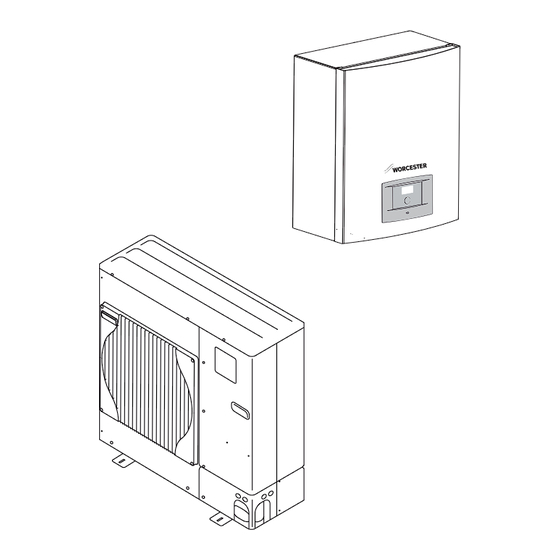
- Page 1 INSTALLATION, COMMISSIONING AND SERVICING INSTRUCTIONS AIR TO WATER SPLIT HEAT PUMP GREENSOURCE HYDROLIGHT AND HYDROCOMFORT OUTDOOR UNIT 7.5, 10, 11 AND 12, 1 PHASE AND 3 PHASE MODELS HYDROLIGHT 8 AND 16 1 PHASE HYDROCOMFORT 8 AND 16 1 PHASE AND 3 PHASE 6 720 648 135-00.1I UK/IE...
-
Page 2: Table Of Contents
TABLE OF CONTENTS TABLE OF CONTENTS 10 Electrical connection ....... . . 23 10.1 Connecting the heat pump . -
Page 3: Key To Symbols And Safety Instructions
KEY TO SYMBOLS AND SAFETY INSTRUCTIONS 16.8 Screed drying ....... . . 62 •... -
Page 4: Benchmark
Renewable Heat Incentive (RHI). The Worcester Bosch Group design team offer a heat pump sizing service which is MCS compliant. To request this service, download and submit the form using the guidance notes from our website address: www.worcester-bosch.co.uk/hp... -
Page 5: Regulations And Standards
This is to certify that the above ranges of products manufactured by Bosch Thermotechnology have been tested and found to comply with: • the requirements of the (Water Fittings) Regulations 1999 for England and Wales, the Water Byelaws 2000, Scotland and the Water Regulations Northern Ireland. -
Page 6: Standard Delivery
STANDARD DELIVERY STANDARD DELIVERY 6 720 648 135-13.2I Fig. 1 Standard delivery, Hydrolight/Hydrocomfort 8 module Hydrolight/Hydrocomfort module (example) Installation instructions and operating instructions Cable gland X 2 Particle filter with strainer Circlip pliers Jumpers for 1-phase installation X 2 Male adapter part 22 mm (Hydrocomfort X 1, Hydrolight X 1) Female adapter part 22 mm (Hydrocomfort X 1, Hydrolight X 3) Washer 1”... - Page 7 STANDARD DELIVERY 6 720 648 135-13.2I Fig. 2 Standard delivery, Hydrolight/Hydrocomfort 16 module Hydrolight/Hydrocomfort module (example) Installation instructions and operating instructions Cable gland X 2 Particle filter Circlip pliers Jumpers for 1-phase installation X 2 Male adapter part 28 mm (Hydrocomfort X 1, Hydrolight X 1) Female adapter part 28 mm (Hydrocomfort X 1, Hydrolight X 3) Washer 1”...
-
Page 8: General
6 720 648 125-02.1I Fig. 3 Standard delivery, ODU 7.5 ODU 7.5 6 720 648 125-84.1I Fig. 4 Standard delivery, ODU 10 / 11 / 12 ODU 10 / ODU 11 / ODU 12 Hydrolight Greensource Split HP Hydrolight 8kW Single-phase... -
Page 9: Application Area
BS EN 12828. defrosting. During defrosting, the flow in the refrigerant circuit is Other forms of use are not permitted. Worcester, Bosch group take no reversed by means of an electrically-controlled four-way valve. responsibility for damage occurring due to non-permitted use. -
Page 10: Can-Bus Termination
GENERAL CAN-BUS TERMINATION A method for good ESD protection is a ground-connected bracelet when handling electronics. This bracelet must be put on before opening the screened metal bag/packaging or before exposing an installed board. The bracelet must be worn until the circuit board is enclosed in its screen packaging or closed electric box. -
Page 11: Dimensions, Clearance And Pipe Connections
Any protective roof must be installed at least 1 metre above the outdoor unit, to prevent recirculation of cold air. 1000 6 720 644 816-10.2I Fig. 11 ODU 10, 11 and ODU 12, dimensions in mm 6720648125-07.1I Fig. 9 Dimensions in mm 6 720 806 629 (2013/02) -
Page 12: Installation Location
DIMENSIONS, CLEARANCE AND PIPE CONNECTIONS 8.1.3 INSTALLATION LOCATION Heat pump installations should be made in accordance to the current MIS3005 micro generation installation standards and including MCS020 planning standards and Manufacturers instructions, suitable mounting components are available as accessories. WARNING: Risk of damage ▶... -
Page 13: Appliance Layout
DIMENSIONS, CLEARANCE AND PIPE CONNECTIONS 8.1.4 APPLIANCE LAYOUT 6720648125-09.2I Fig. 13 outdoor unit (example shows ODU 12) Connections, electric and signal cable Cable terminals Connection, liquid (during heating mode) Connection, hot gas (during heating mode) Shut-off valves, liquid and hot gas Compressor Service outlet at shut-off valve for liquid (connection for vacuum pump) -
Page 14: Hydrolight/Hydrocomfort Unit
DIMENSIONS, CLEARANCE AND PIPE CONNECTIONS HYDROLIGHT/HYDROCOMFORT UNIT PIPE CONNECTIONS During the installation, the front panel of the Adapter parts delivered with the appliance are only for Hydrolight/Hydrocomfort unit can be removed and water connections. placed on the hooks on the left or the right side of the ▶... - Page 15 DIMENSIONS, CLEARANCE AND PIPE CONNECTIONS 6 720 644 816-12.2I Fig. 16 Pipe connections of dual mode Hydrolight unit, with mixing valve for 2. heat appliance. Liquid line Discharge water from the safety valve 6 720 648 131-25.1I Return (back to boiler) Fig.
-
Page 16: Installation
INSTALLATION INSTALLATION POSITIONING Only competent installers may carry out the installation. ▶ Remove the supplied accessories. The installer must follow all current rules and regulations ▶ Remove the packaging according to the instructions on the packaging. and recommendations from the manufacturer. CONNECT THE HEAT PUMP TO THE HEATING SYSTEM ACCESSORIES Heat losses can be reduced by keeping the lengths of... -
Page 17: Connecting The Refrigerant Pipe
• Flaring tool ▶ In cases where all attempts to find a micro leak have • Flaring gauge failed, Worcester, Bosch Group supports the use of • Vacuum pump adapter Fernox F4 leak sealer. • Electronic refrigerant scales... - Page 18 INSTALLATION ▶ Put the flange nut on the liquid pipe (measures: table 5). 9.7.3 CONNECTING THE EXTERNAL AND INTERNAL UNITS ▶ Lay out the connection pipes according to how you intend to install them between the internal and external unit of the heat pump. Start connecting the pipes at the indoor unit.
-
Page 19: Liquid Side
INSTALLATION ▶ Open the shut-off valve by turning the screw ( [2], fig. 22) as far as 9.7.7 FILLING WITH REFRIGERANT it will go using a 5 mm socket wrench (7.5 kW), or by turning the ▶ Subsequent filling of the system is not required if the length of the handle (10–12 kW). -
Page 20: Filling The Heating System
9.8.1 FILLING THE HEATING SYSTEM WITH CLEAN WATER Worcester Bosch recommends the fitting of an inline system filter to help ensure that the heating system can perform at its optimum level. ▶ Set the pre-pressure for the expansion vessel in the premises according to the heating unit's static height. -
Page 21: Connecting A Heat Pump Dhw Cylinder (3Rd Party)
INSTALLATION CONNECTING A HEAT PUMP DHW CYLINDER (3RD 9.9.1 HEAT PUMP HOT WATER CYLINDER, SOLAR PARTY) A heat pump solar hot water cylinder can also be connected to either the Hydro light or the Hydro comfort. It is very important that only DHW storage cylinders specifically designed for use with heat pumps are used. -
Page 22: 3-Way Valve (Accessory)
INSTALLATION 9.10 3-WAY VALVE (ACCESSORY) System configuration with DHW cylinder ( fig. 53, 55 and 57) requires a 3-way valve (E21.Q21). 6 720 617 643-10.2I Fig. 29 Connections in Molex plug 3-way valve E21.Q21 For connection to the indoor unit ( fig. 41 or fig. 47). 9.11 INSULATION 6 720 617 643-06.1I All system heat pipe work should be insulated to current standards... -
Page 23: Other Connections
ELECTRICAL CONNECTION For the settings in the Hydrolight/Hydrocomfort unit, refer to chapter 16.5. 9.15 DISCONNECTING ACCESSORIES 0,3 m CAUTION: Before resetting to factory values, make a note of parameters that were set when the heat pump was commissioned (heat curve, set point values, programs...) If an accessory that has been installed is to be disconnected from the 0,3 m... -
Page 24: Connecting The Heat Pump
▶ Install a separate safety switch that cuts all current to the heat pump. A safety switch for each supply is required for separate power supplies. Worcester Bosch recommend the fitting of a separate electric meter on the electrical supply from the Hydrolight/ Hydrocomfort to the main electric meter. - Page 25 ELECTRICAL CONNECTION 10.1.1 ADJUSTMENT OF SW8 10.1.3 ALARM SIGNAL, MIXED ADDITIONAL HEAT Switch SW8-3 on the printed circuit board of the external unit must With an external 2nd heat appliance, the alarm signal to E71.E1.F21 always be in the ON position because connection S1 is not used to (230 V) is connected to the terminal J4 of the main board (IOB-A) in the supply power to the PAC board.
-
Page 26: Connecting The Hydrolight/Hydrocomfort Module
ELECTRICAL CONNECTION 10.1.5 ZONE VALVE FOR THE HYDROLIGHT UNIT WITH 2ND HEAT APPLIANCE AND FLOW RATE CONTROL When using a Hydrolight unit with a mixer and a 2nd heat appliance equipped with flow monitoring (mainly wall-mounted boilers containing a small amount of water or modulating boilers), a zone valve must be installed between the external heater and the internal unit. -
Page 27: Pcb Layout In Control Panel, Hydrolight Unit
ELECTRICAL CONNECTION 10.4 PCB LAYOUT IN CONTROL PANEL, HYDROLIGHT UNIT 6 720 648 135-25.1I Fig. 37 Layout in control panel, Hydrolight unit Interface board (PAC) Main board (IOB-A) Accessories board (IOB-B, not included in standard delivery) Terminal (X1) 6 720 806 629 (2013/02) -
Page 28: Switch Settings, Hydrolight Unit
ELECTRICAL CONNECTION 10.5 SWITCH SETTINGS, HYDROLIGHT UNIT 6 720 803 724-12.2I Fig. 38 Switch settings for Hydrolight unit with additional mixed heating circuit (accessory) [Solid line = factory connected] [Dotted line = connected at installation] Switch Interface board Main board Accessories board in Multi Box room temperature controller room temperature controller... -
Page 29: Power Supply, Hydrolight Unit And Additional Mixed Heating Circuit (Accessory)
ELECTRICAL CONNECTION 10.6 POWER SUPPLY, HYDROLIGHT UNIT AND ADDITIONAL MIXED HEATING CIRCUIT (ACCESSORY) 6 720 803 724-15.1I Fig. 39 Power supply, Hydrolight unit and additional mixed heating circuit (accessory) Accessories board (IOB-B, not included in standard delivery) Main board Interface board Mains power supply 6 720 806 629 (2013/02) -
Page 30: Terminal Connection Diagram, Hydrolight Unit With 2Nd Heat Appliance
ELECTRICAL CONNECTION 10.7 TERMINAL CONNECTION DIAGRAM, HYDROLIGHT UNIT WITH 2ND HEAT APPLIANCE 6 720 644 816-24.5I Fig. 40 Terminal connection diagram, Hydrolight unit with 2nd heat appliance [Solid line = factory connected] [E21.E112] Heating cable [Dotted line = connected at installation] [E71.E1.F21]Alarm signal, 2nd heat appliance (~230V) Hydrolight unit (main board) [E71.E1.E1] Start signal, 2nd heat appliance... -
Page 31: Wiring Diagram, Hydrolight Unit With 2Nd Heat Appliance
ELECTRICAL CONNECTION 10.8 WIRING DIAGRAM, HYDROLIGHT UNIT WITH 2ND HEAT APPLIANCE Fig. 41 Wiring diagram, Hydrolight unit with 2nd heat appliance [E21.Q21] 3-way valve (accessory) [E11.G1] Heating circuit pump, heating system [Solid line = factory connected] [E21.G2] DHW circulation pump, heating water [Dotted line = connected at installation] [E21.E112] Heating cable Hydrolight module... -
Page 32: Signal Cable, Hydrolight Unit With 2Nd Heat Appliance
ELECTRICAL CONNECTION 10.9 SIGNAL CABLE, HYDROLIGHT UNIT WITH 2ND HEAT APPLIANCE 6 720 648 135-09.2I Fig. 42 Signal cable, Hydrolight unit with 2nd heat appliance [13] Stage/Capacitor [14] Display board Mains power supply [15] Main board Interface board Terminal S2, S3 Malfunctions Compressor off/on defrosting... -
Page 33: Layout In Control Panel, Hydrocomfort Unit With Electr. Heater
ELECTRICAL CONNECTION 10.10 LAYOUT IN CONTROL PANEL, HYDROCOMFORT UNIT WITH ELECTR. HEATER 6 720 803 724-14.1I Fig. 43 Layout in control panel, Hydrocomfort unit with electr. heater Interface board (PAC) Main board (IOB-A) Accessories board (IOB-B, not included in standard delivery) Relay 1 (K1) Relay 2 (K2) Terminal (X1) -
Page 34: Switch Settings, Hydrocomfort Unit With Electr. Heater And Additional Mixed Heating Circuit (Acc)
ELECTRICAL CONNECTION 10.11 SWITCH SETTINGS, HYDROCOMFORT UNIT WITH ELECTR. HEATER AND ADDITIONAL MIXED HEATING CIRCUIT (ACC) 6 720 803 724-12.2I Fig. 44 Switch settings, Hydrocomfort module with electr. unit heater and additional mixed heating circuit (accessory) [Solid line = factory connected] [Dotted line = connected at installation] Switch Interface board... -
Page 35: Power Supply, Hydrocomfort Unit With Electr. Heater
ELECTRICAL CONNECTION 10.12 POWER SUPPLY, HYDROCOMFORT UNIT WITH ELECTR. HEATER 6 720 803 724-10.1I Fig. 45 Power supply, electr. heater, 3-phase Thermal Protection Accessories card (not included in standard delivery) Main board Interface board Electric heater Mains power supply 6 720 806 629 (2013/02) -
Page 36: Terminal Connection Diagram, Hydrocomfort Unit With Electr. Heater
ELECTRICAL CONNECTION 10.13 TERMINAL CONNECTION DIAGRAM, HYDROCOMFORT UNIT WITH ELECTR. HEATER 6 720 806 629-10.1I Fig. 46 Terminal connection diagram, Hydrocomfort unit with electr. heater [Solid line = factory connected] [Dotted line = connected at installation] Hydrocomfort module (main board) outdoor unit Safety switches (not included in standard delivery) Fuse, outdoor unit... -
Page 37: Wiring Diagram, Hydrocomfort Unit With Electr. Heater
ELECTRICAL CONNECTION 10.14 WIRING DIAGRAM, HYDROCOMFORT UNIT WITH ELECTR. HEATER 6 720 648 125-29.4I Fig. 47 Wiring diagram, Hydrocomfort unit with electr. heater [E21.E2.K11]Electric heater, stage 1 [E21.E2.K12]Electric heater, stage 2 [Solid line = factory connected] [E21.Q21] 3-way valve (accessory) [Dotted line = connected at installation] [E11.G1] Heating circuit pump, heating system... -
Page 38: Signal Cable, Hydrocomfort Unit With Electr. Heater
ELECTRICAL CONNECTION 10.15 SIGNAL CABLE, HYDROCOMFORT UNIT WITH ELECTR. HEATER 6 720 648 135-08.2I Fig. 48 Signal cable, Hydrocomfort unit with electr. heater [13] Stage/Capacitor [14] Display board Mains power supply [15] Main board Interface board [16] Pressure Switch Terminal S2, S3 Malfunctions Compressor off/on defrosting... -
Page 39: Technical Information
TECHNICAL INFORMATION TECHNICAL INFORMATION 11.1 SPECIFICATION - OUTDOOR UNIT Unit ODU 7.5s ODU 10s ODU 11s ODU 12s ODU 11t ODU 12t 8 kW 11 kW 14 kW 16 kW 14 kW 16 kW Operation, air/water Rated output at A7/W35 11.9 14.0 16.0... -
Page 40: Specification, Hydrolight Unit With 2Nd Heat Appliance
TECHNICAL INFORMATION HEATING OPERATION RANGE FOR THE OUTDOOR UNIT T1( °C) T2 (°C) 6 720 648 125-85.2I Fig. 49 ODU 7,5 - 12 [T1] Flow temperature [T2] Outdoor temperature 11.2 SPECIFICATION, HYDROLIGHT UNIT WITH 2ND HEAT APPLIANCE Hydrolight 8 Hydrolight 16 Electr. -
Page 41: Specification - Hydrocomfort Unit With Electr. Heater
TECHNICAL INFORMATION 11.3 SPECIFICATION - HYDROCOMFORT UNIT WITH ELECTR. HEATER Hydrocomfort 8 Hydrocomfort 8 Hydrocomfort 16 Hydrocomfort 16 Electr. data Mains power supply 230V 1N AC 50Hz 400V 3N AC 50Hz 230V 1N AC 50Hz 400V 3N AC 50Hz Recommended automatic circuit breaker 45 A 16 A 45 A... -
Page 42: System Configurations
TECHNICAL INFORMATION 11.4 SYSTEM CONFIGURATIONS 11.4.1 SYSTEM CONFIGURATION EXPLANATIONS Electricity/oil/gas boiler (2. heat appliance) E10.T2 Outside temperature sensor E71.E1.C101 Expansion vessel Table 11 E10 E71.E1.F101 Safety valve Heating circuit without mixer E71.E1.F111 Automatic air vent valve E11.G1 heating circuit pump (not in standard delivery) E71.E1.G71 Circulation pump 2nd heat appliance (optional ... - Page 43 TECHNICAL INFORMATION 11.4.3 SYSTEM CONFIGURATIONS 6 720 648 135-18.2I Fig. 53 Hydrocomfort with DHW cylinder and central heating Hydrocomfort The particle filter [E21.V101] is installed horizontally in Outdoor unit (ODU) the return heating pipe to the Hydrolight/Hydrocomfort , Indoor unit with internal electrical additional heat serving central heating and hot water cylinder.
- Page 44 TECHNICAL INFORMATION 6 720 648 135-19.2I Fig. 54 Additional external heater with mixer The particle filter [E21.V101] is installed horizontally in Hydrolight the return heating pipe to the Hydrolight/Hydrocomfort , Outdoor unit (ODU) Indoor unit with external boiler additional heat serving central heating. 6 720 806 629 (2013/02)
- Page 45 TECHNICAL INFORMATION E71.E1.G71 6 720 648 135-24.3I Fig. 55 Additional external heater with mixer with DHW cylinder The particle filter [E21.V101] is installed horizontally in Hydrolight the return heating pipe to the Hydrolight/Hydrocomfort , Outdoor unit (ODU) [E71.E1.G71]Circulation pump for 2nd heat appliance, regulated by the 2nd heat appliance (...
- Page 46 TECHNICAL INFORMATION 6 720 648 135-21.4I Fig. 56 Indoor unit with external boiler additional heat serving central The particle filter [E21.V101] is installed horizontally in heating through a buffer tank. the return heating pipe to the Hydrolight/Hydrocomfort , Hydrolight indoor unit. Outdoor unit (ODU) 6 720 806 629 (2013/02)
- Page 47 TECHNICAL INFORMATION 6 720 135-20.5I Fig. 57 External boiler additional heat serving central heating through a buffer tank. External Solar panels serving cylinder. 6 720 806 629 (2013/02)
- Page 48 TECHNICAL INFORMATION 11.4.5 TEMPERATURE SENSOR TEST VALUES The particle filter [E21.V101] is installed horizontally in HYDROLIGHT/HYDROCOMFORT UNIT the return heating pipe to the Hydrolight/Hydrocomfort , Temperature sensor in, or connected to, the Hydrolight/Hydrocomfort unit (T1, T2, T3, T5, T8, T9) has the measured value in accordance with table 18.
-
Page 49: General System Information
GENERAL SYSTEM INFORMATION HIGH TEMPERATURE SENSOR ODU R(kΩ) The temperature sensors TH4 (hot gas) and TH32 (compressor temperature) show measured values in accordance with table 22 and the diagram in fig. 60. k k °C °C T... T... 17,5 13,0 Table 22 The resistance values, high temperature sensor... -
Page 50: Control Method For Compressor
USER INTERFACE • Outside temperature sensor and room temperature controller EXAMPLE: THE HEAT CURVE IS SET AT 55 °C AT –5 °C (NOT (one room temperature controller can be used for each heating FACTORY SETTING): circuit): if the system is to be controlled using an outside temperature sensor and a room temperature controller, the outdoor sensor must be located on the north facing external wall of the house. -
Page 51: Control Panel Function
INSTALLATION AND SERVICE MENU (I/S) MENU DISPLAY 13.3 MENU TABS The menus are divided into four different tabs for different reasons. • Temperature - overview of heating settings • Blocking - blocking functions • Menu - the most popular menu items •... -
Page 52: Menu Overview
MENU OVERVIEW MENU OVERVIEW Here you find the upper levels for all functions under Menu and Advanced. All setting functions are also in the table Factory settings (Chapter 19.1). Installer level (I/S) = [1], User level = [0]. Menu Access level Fast restart of heat pump Start up Language... - Page 53 MENU OVERVIEW Menu Access level Manual operation Manual operation Manual operation time 3-way valve G1 heating system pump G2 Heat carrier pump G2 Speed Compressor Cooling (non Function) Electric water heater step 1 Electric water heater step 2 External additional heater Mixing valve open Mixing valve close Mixing valve open, heating system 2...
- Page 54 MENU OVERVIEW Blocking Access level Block additional heat Select Yes/No Block hot water Select Yes/No Block heating Select Yes/No Block heat, Select Yes/No heating system 2 Table 24 Blocking Advanced menu Heating/Cooling Minimum outdoor temperature of heat curve Heating system temperature Heat curve Hysteresis --Quick acceleration...
- Page 55 MENU OVERVIEW Advanced menu Temperature heating system 2 Heat curve (only if installed) Room sensor settings --Room temperature setting --Room sensor influence Time limited settings ---Time control heating ---Day and time --Change in temperature --Time control cooling day/time --Holiday ---Date ---Change in temperature --External input 1 --External input 2...
- Page 56 MENU OVERVIEW Advanced menu Additional heat Start delay settings Time control additional heat Operating option Additional heat only Block additional heat Electric additional heat settings Connection capacity --State total output --Compressor mode, output limitation --Additional heat only, output limitation Ramp time increase Ramp time decrease Locking of electricity supply when defrosting Neutral zone...
-
Page 57: Commissioning
COMMISSIONING ▶ Set date in the format Year-Month-Day. COMMISSIONING WARNING: The compressor must be warmed up before starting for the first time. ▶ Switch on the power to the outdoor unit at least 2 hours prior to commissioning, up to 12 hours for 6 720 648 149-24.1I extreme climate conditions (below -15 °C ambient Fig. -
Page 58: Manual Operation
COMMISSIONING 6 720 648 148-49.1I 6 720 648 135-14.1I Fig. 76 Fig. 73 ▶ To activate manual mode, select Yes then Save under the Manual ▶ Select E11.T1 Set point maximum, i.e. the max. permitted flow operation menu item. temperature (H-value). The setting can be between 20°C and 80°C, Three-way valves, circulation pumps, compressor, electric elements the factory setting is 45°C. - Page 59 COMMISSIONING ▶ Select Operating option Only the part of the heat curve with flow temperature up ▶ Select Additional heat only. to the highest permitted flow temperature (the H-value) ▶ Select Yes and then Save. Heating and hot water is only supplied via is shown in the window.
-
Page 60: Domestic Hot Water Settings
COMMISSIONING 16.3.8 BLOCK HEAT PUMP AT LOW OUTDOOR TEMPERATURE OUTDOOR TEMPERATURE DISPLAY IN ROOM SENSOR YES/NO With Yes the room controller displays the temperature in the house and the temperature outdoors alternately. 16.4 DOMESTIC HOT WATER SETTINGS ▶ In I/S select Advanced ▶... -
Page 61: Settings For Heating Circuit 2
COMMISSIONING the desired number of hours have passed, the heat pump returns to the external input is no longer active, the control unit returns to normal normal hot water mode. mode. Select pre-configuration of the heat pump if External input, heating DANGER: Risk of burn injuries. -
Page 62: Fast Restart Of Heat Pump
COMMISSIONING 16.6.4 CORRECT SENSOR The opposite applies if T1 falls below the heat curve by 5° instead, the speed then increases (advances). All sensors can be corrected a maximum of 5 °C up or down. The value is given directly in °C. Sensors should only be corrected in exceptional Setting the permissible temperature deviation: cases. -
Page 63: Timer (Timer Programs)
TIMER (TIMER PROGRAMS) means that all functions, apart from the safety functions and electric TIMER (TIMER PROGRAMS) heating only operation, are deactivated. When drying the screed, all heating circuits are in operation. The screed drying is carried out in three phases: •... -
Page 64: Error Management
ERROR MANAGEMENT If you press the rotary selector, Acknowledge is marked, the alarm ERROR MANAGEMENT symbol disappears and the warning signal is suppressed. The heat pump restarts if heat demand exists. Alarms in the display window apply mainly to the Hydrolight/ The alarm symbol (... - Page 65 ERROR MANAGEMENT Possible cause 3; maximum flow temperature incorrectly set ▶ Check termination settings in the room controller. ▶ Check the power supply on CAN-BUS. The voltage should be 12V DC. ▶ With separate domestic hot water heating, the anticipated ▶...
-
Page 66: Warning Message
ERROR MANAGEMENT 18.6.14 FAULT ON ELECTRIC ELEMENT 18.7.3 HIGH TEMPERATURE DIFFERENCE HEAT TRANSFER FLUID 6 720 649 018-04.1I 6 720 648 148-56.1I Fig. 91 Fig. 89 This warning window is displayed when the temperature difference Possible cause 1: overheating protection of the power supply has between sensors T8 and T9 becomes too high (>... -
Page 67: Checking The Heat Pump Using The Diagnostic Tool (Accessory)
ERROR MANAGEMENT Possible cause 2; bivalence point set incorrectly Block heat pump at low outdoor temperature . ▶ Adjust bivalance point ( 16.3.8). Possible cause 3; flow rate fault ▶ Check filters and valves 6 720 614 486-35.1I 18.9.4 MAXIMUM FLOW TEMPERATURE, ADDITIONAL HEAT Fig. -
Page 68: Refrigerant Circuit Diagram
ERROR MANAGEMENT 18.10.2 REFRIGERANT CIRCUIT DIAGRAM TH32 TH33 6 720 644 816-59.1I Fig. 94 Refrigerant circuit, ODU 7.5 4-way valve High pressure switch 63H Compressor Expansion valve A Liquid separator Expansion valve B Shut-off valve Refrigerant liquid pipe Refrigerant gas pipe [10] Service output [TH32]Temperature sensor, compressor [TH33]Temperature sensor, surroundings... - Page 69 ERROR MANAGEMENT TH32 TH33 6 720 644 816-60.1I Fig. 95 Refrigerant circuit, ODU 10 4-way valve High pressure switch 63H Compressor Expansion valve A Liquid separator Expansion valve B Shut-off valve Refrigerant liquid pipe Refrigerant gas pipe [10] Service output...
- Page 70 ERROR MANAGEMENT TH32 TH33 6 720 644 816-61.1I Fig. 96 Refrigerant circuit, ODU 12 4-way valve High pressure switch 63H Compressor Expansion valve A Liquid separator Expansion valve C Expansion valve B Shut-off valve Refrigerant liquid pipe [10] Refrigerant gas pipe [11] Service output [TH32]Temperature sensor, compressor [TH33]Temperature sensor, surroundings...
-
Page 71: Factory Settings
FACTORY SETTINGS Advanced menu Level F value FACTORY SETTINGS Heating/cooling _”_\Minimum outdoor temperature of heat –10 °C 19.1 FACTORY SETTINGS curve The tables show the values that have been preset at the factory (factory _”_Heating system temperature settings). These values can be modified by the user [0] via user levels _”_\_”_\Heat curve V=20.0 °C Menu and Advanced. - Page 72 FACTORY SETTINGS Advanced menu Level F value Advanced menu Level F value _”_\_”_\_”_\Holiday Additional heat settings _”_\_”_\_”_\_”_\Date _”_\Start delay 60 min _”_\_”_\_”_\_”_\Change in temperature -10 °C _”_\Time control additional heat _”_\_”_\_“_\External input _”_\Operating option _”_\_”_\_”_\Active if Closed _”_\_”_\Additional heat only _”_\_”_\_”_\Change in temperature 0 °C _”_\_”_\Block additional heat...
-
Page 73: Functional Check
ENVIRONMENTAL PROTECTION Environmental protection is a fundamental corporate strategy of the Bosch Group. DANGER: Discharge of poisonous gases! The quality of our products, their economy and environmental safety are The refrigerant circuit contains materials that can form... -
Page 74: Particle Filter
Terms and conditions. To read the full Terms and Conditions please visit us online at www.worcester-bosch.co.uk/guarantee. The Guarantee Registration form is available on this same page and can be completed and submitted electronically. Alternatively please telephone one of our Guarantee Registration advisors on 0844 892 2552. -
Page 75: Commissioning Report
COMMISSIONING REPORT COMMISSIONING REPORT Commissioning date: Customer address: Surname, first name: Street, house number: Town: Telephone: Specialist contractor: Surname, first name: Street: Town: Telephone: Appliance data: Appliance type: Part no.: Serial number: FD no.: Installation test steps System components: Confirmation / values ... - Page 76 COMMISSIONING REPORT Yes | No Heating system filled via the determined pre-charge pressure of the expansion vessel to …….. bar ? Yes | No Internal unit sufficiently bled Tightness test carried out for all connections inside and outside the internal unit Yes | No ...
-
Page 77: Inspection And Maintenance Reports
INSPECTION AND MAINTENANCE REPORTS INSPECTION AND MAINTENANCE REPORTS The inspection and maintenance reports are also designed as templates ▶ Sign and date the completed inspection work. and may be photocopied. GENERAL INFORMATION Maintenance report for air to water heat pumps Customer/system user: Surname, first name: Street, house number:... - Page 78 INSPECTION AND MAINTENANCE REPORTS Maintenance report for air to water heat pumps Parameter settings changed : Heat:.............. remarks: DHW settings changed :..... remarks: CH settings changed :...... remarks: Safety settings changed .... remarks: Reset to factory settings :.... remarks: Temperature of heat transfer medium during Off (T8 ) ........
-
Page 79: Benchmark Log Book
BENCHMARK LOG BOOK BENCHMARK LOG BOOK AIR TO WATER HEAT PUMP COMMISSIONING CHECKLIST This Commissioning Checklist is to be completed in full by the competent person who commissioned the heat pump and associated equipment as a means of demonstrating compliance with the appropriate Building Regulations and then handed to the customer to keep for future reference. Failure to install and commission this equipment to the manufacturer’s instructions may invalidate the warranty but does not affect statutory rights. - Page 80 BENCHMARK LOG BOOK Service Record It is recommended that your heating system is serviced regularly and that the appropriate Service Interval Record is completed. Service Provider Before completing the appropriate Service Interval Record below, please ensure you have carried out the service as described in the manufacturer’s instructions.
- Page 81 NOTES 6 720 806 629 (2013/02)
- Page 82 NOTES 6 720 806 629 (2013/02)
- Page 83 NOTES 6 720 806 629 (2013/02)
- Page 84 01905 752571 LITERATURE: 0844 892 9800 TRAINING: 01905 752526 SALES: 01905 752640 Worcester, Bosch Group Cotswold Way, Warndon, Worcester WR4 9SW. Tel. 0844 892 9900 Worcester, Bosch Group is a brand name of Bosch Thermotechnology Ltd. worcester-bosch.co.uk 6 720 806 629...
Need help?
Do you have a question about the ODU 10 and is the answer not in the manual?
Questions and answers